
ESP32 - Slide Switch
Some choices in a project are made once and then left alone: a fan that runs by itself or only by hand, a weather station that sends its data every minute or every hour, a game pad set up for the left hand or the right hand. A tiny slide switch is the right part for such a choice, because its handle stays where you put it. This tutorial shows how to read the DIYables Mini Slide Switch SS12D10 with an ESP32 and print its position, ON or OFF, to the Serial Monitor. You will wire it in two ways: with three wires and no resistor, and with only two wires, using the pull-up resistor inside the ESP32.
This tutorial shows how to program the ESP32 using the Arduino language (C/C++) via the Arduino IDE. If you’d like to learn how to program the ESP32 with MicroPython, visit this ESP32 MicroPython - Slide Switch tutorial.
Hardware Used In This Tutorial
Or you can buy the following kits:
| 1 | × | DIYables ESP32 Starter Kit (ESP32 included) | |
| 1 | × | DIYables ESP32 S3 Starter Kit (ESP32 S3 included) | |
| 1 | × | DIYables Sensor Kit (18 sensors/displays) |
Introduction to the Slide Switch
The DIYables Mini Slide Switch SS12D10 is a very small switch with two positions. Its body is a little metal box, a 5mm plastic handle sticks out of the top, and three pins stand in one row at the bottom. The switch is latching: push the handle to one end, and it stays at that end until you push it back. A push button behaves the other way, because its spring lifts it back the moment you let go. In parts lists, this kind of switch is called SPDT (single pole, double throw), also written 1P2T.
| Mini Slide Switch SS12D10 | |
|---|---|
| The contact type | SPDT (1P2T), 2 positions |
| The number of pins | 3, in one row |
| The pin pitch | 4.7mm |
| The terminal length | 6.9mm |
| The handle length | 5mm |
| The body size | about 12.8 x 6.7 x 18.2mm |
| The mounting | vertical, through-hole |
| The contact material | silver-plated brass |
| The contact rating | AC 125V 2A |
| The lifetime | more than 100,000 switching cycles |
| The operating temperature | -25°C to 80°C |
Do not let the 125V 2A rating worry you. It is the most current the contacts can carry. In this tutorial, the switch only passes a tiny signal current into one ESP32 pin.
Slide Switch Pinout
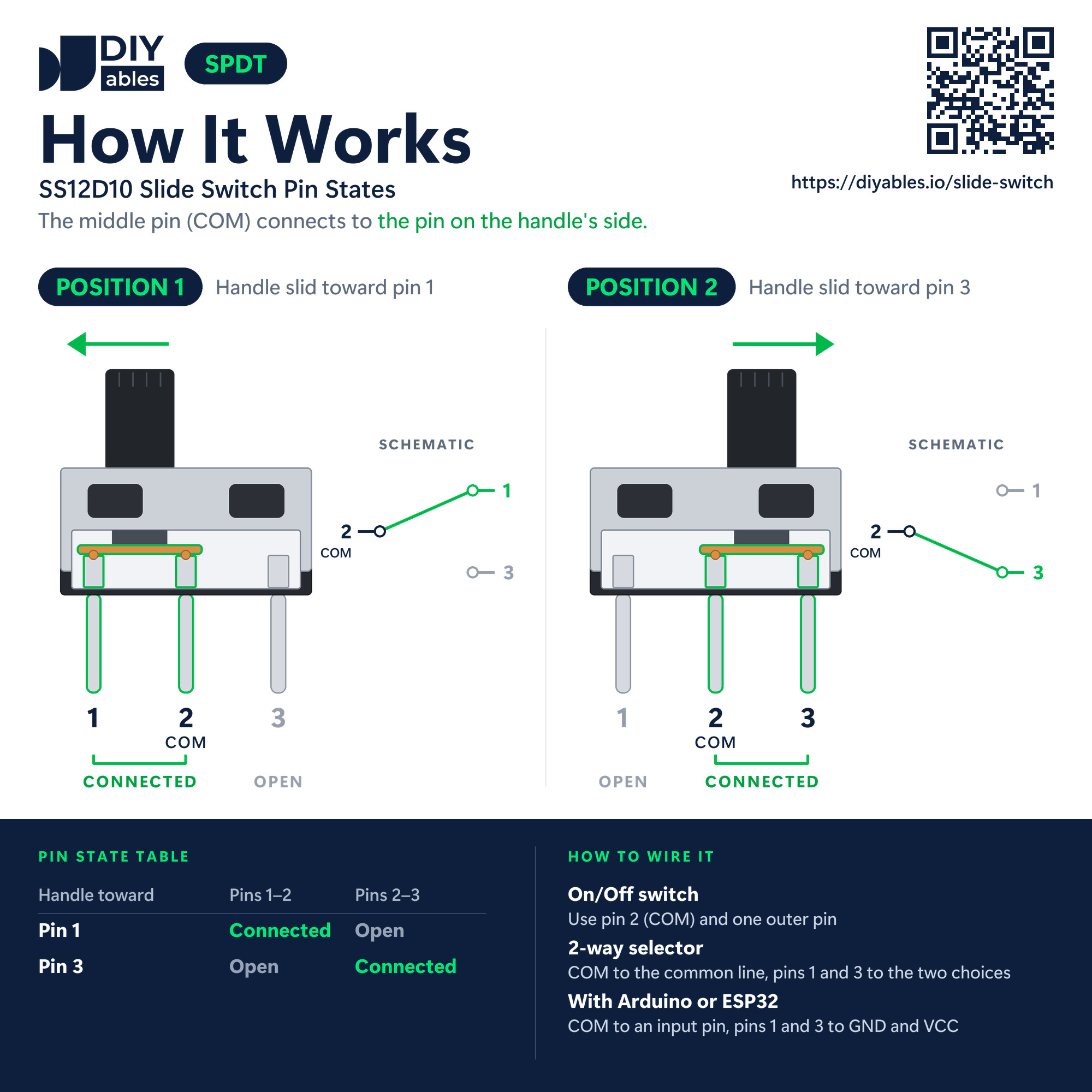
Nothing is printed on the switch, so just count the pins. The middle one is always COM:
- Pin 1: one of the outer pins. Connect this pin to GND (0V).
- Pin 2 (COM): the middle pin, the common one. Connect this pin to GPIO21 of the ESP32.
- Pin 3: the other outer pin. Connect this pin to 3V3 of the ESP32 (only in the 3-wire version).
The trick is a small metal bridge that slides along with the handle. One end of it always touches COM. The other end touches the outer pin on the same side as the handle:
- Handle toward pin 1: pin 1 and COM are connected. Pin 3 is open.
- Handle toward pin 3: COM and pin 3 are connected. Pin 1 is open.
So when pin 1 is on GND and pin 3 is on 3V3, COM simply jumps between 0V and 3.3V. The ESP32 reads LOW or HIGH, and the code calls them OFF and ON. One more detail: when the bridge slides, it rattles on the pin for a few milliseconds. The ESP32 is fast enough to see this rattle as several quick changes, so the code reads the pin twice, 50 milliseconds apart.
Do not mix up this part with its cousins. The big ON/OFF rocker switch for a panel is covered in ESP32 - Switch, and a key that springs back is covered in ESP32 - Button Module. A DIP switch is a row of tiny slide switches in one block, see ESP32 - DIP Switch.
Wiring Diagram
Three wires connect the switch to the ESP32, and no resistor is needed. Pin 1 holds one side of the switch at GND, and pin 3 holds the other side at 3.3V. In every handle position, COM is tied to one of them, so GPIO21 never floats.
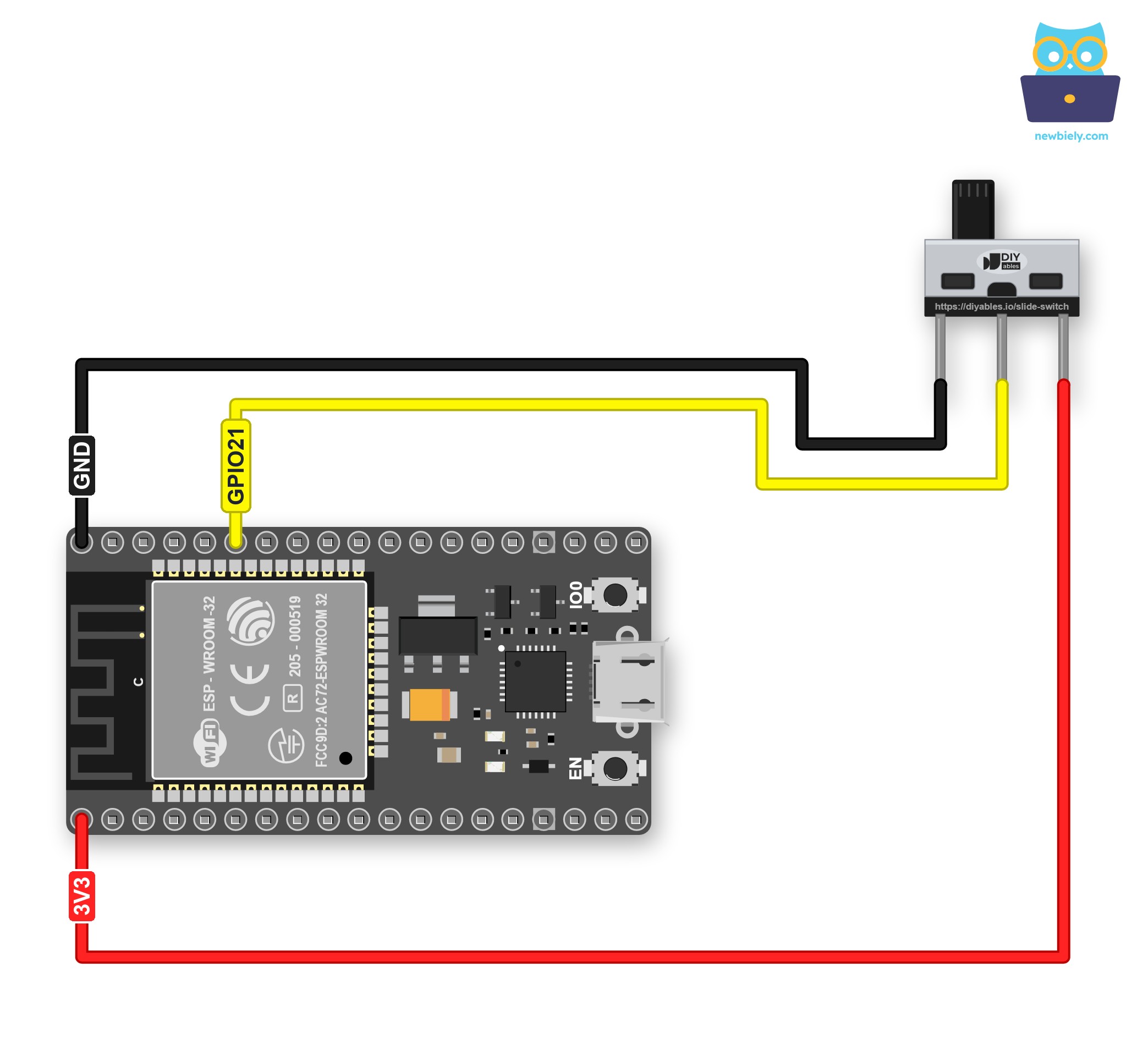
This image is created using Fritzing. Click to enlarge image
| Slide Switch Pin | ESP32 Pin |
|---|---|
| Pin 1 | GND |
| Pin 2 (COM) | GPIO21 |
| Pin 3 | 3V3 (not 5V, not VIN) |
※ NOTE THAT:
Pin 3 must go to the 3V3 pin of the ESP32, never to 5V or VIN. When the handle is toward pin 3, COM passes the voltage of pin 3 straight into GPIO21. Every GPIO of the ESP32 is made for 3.3V at most, so 5V there can damage the pin.
One more rule for the code: GPIO21 stays an input. Never switch it to OUTPUT while the switch is wired: the switch connects the pin directly to 3V3 or GND, and an output that drives the other level makes a short circuit.
Why GPIO21? It is a plain I/O pin with no job while the ESP32 boots, and it has an internal pull-up resistor, which the 2-wire version below needs. You can move COM to another GPIO, but avoid the boot pins GPIO0, GPIO2, GPIO12 and GPIO15, and the flash pins GPIO6 to GPIO11. If your project also has an I2C display, keep in mind that GPIO21 is the default SDA pin. In that case, wire the switch to another free pin, such as GPIO19, and change the number in the code.
If you're unfamiliar with how to supply power to the ESP32 and other components, you can find guidance in the following tutorial: The best way to Power ESP32 and sensors/displays.
How To Program For Slide Switch
Reading a slide switch needs no library. A few built-in functions are enough.
- Give GPIO21 a name and set it as a plain input. INPUT is enough, since the switch itself drives the pin HIGH or LOW.
- Read the pin with digitalRead(). HIGH means the handle is toward pin 3 (ON). LOW means it is toward pin 1 (OFF).
- To spot a move, save the last level in a variable and compare each new reading with it. If they differ, wait 50 milliseconds, read once more, and accept the change only if it is still there.
ESP32 Code - Slide Switch
When the ESP32 starts, this code prints the handle position once. After that, it prints only when you slide the handle to the other end, so the Serial Monitor stays quiet while nothing happens.
Quick Instructions
- If this is the first time you use ESP32, see how to setup environment for ESP32 on Arduino IDE.
- Do the wiring as in the diagram above: pin 1 to GND, COM to GPIO21, pin 3 to 3V3.
- Connect the ESP32 board to your PC with the USB Type-C cable.
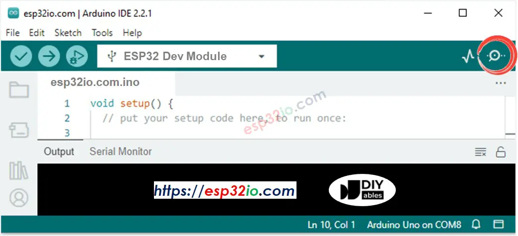
- Open Arduino IDE and select the right ESP32 board (e.g. ESP32 Dev Module) and COM port.
- Copy the code above and paste it into Arduino IDE.
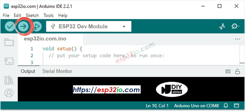
- Click to the Upload button. Arduino IDE compiles the code and uploads it to the ESP32.
- Open the Serial Monitor and choose 9600 baud in its lower right corner.
- Press the EN button on the ESP32 once, so the start line is printed again while the Serial Monitor is open.
- Slide the handle from end to end five times, and stop for a second at each end.
The first two lines come from the start. Then each of the five moves gives exactly one line, even though the contacts bounce. If you see a few strange characters before the first line, do not worry: those are the boot messages of the ESP32, which are sent at 115200 baud. If ON shows up while the handle points to pin 1, the GND and 3V3 wires are swapped. Swap the two outer wires, and the words will match again.
ESP32 Code - Slide Switch with INPUT_PULLUP (2 Wires)
Every wire you save is one less wire that can come loose, and one less pin taken on the ESP32. This version gets rid of the 3V3 wire. Just remove the pin 3 wire. GPIO21 has a pull-up resistor inside the ESP32 chip, and INPUT_PULLUP turns it on, so the pin rests at 3.3V while COM is not joined to GND.
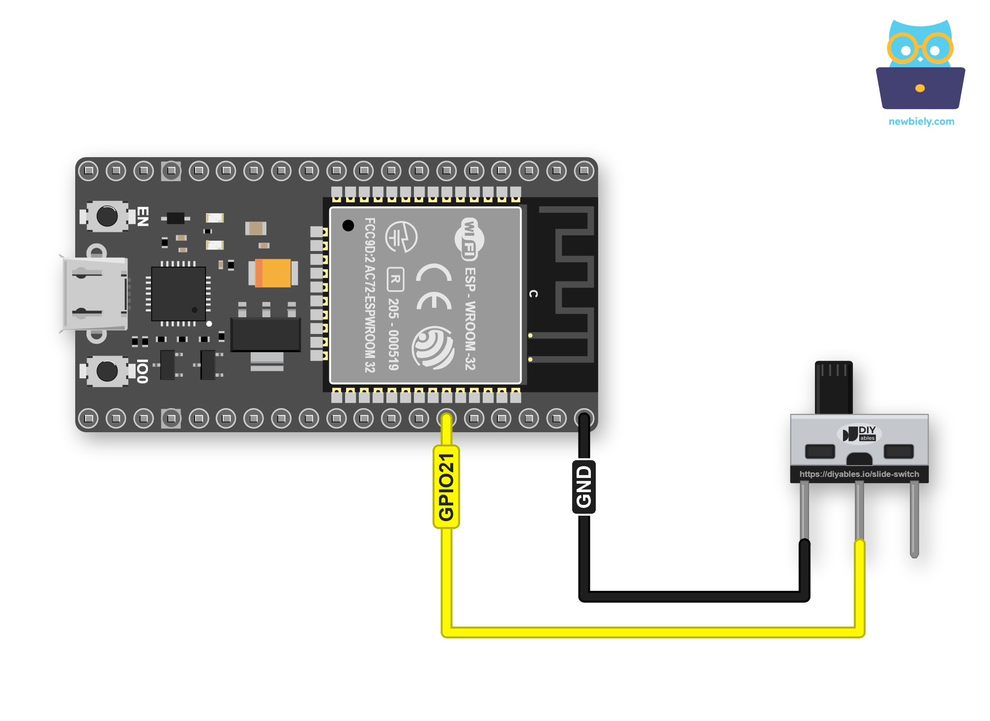
This image is created using Fritzing. Click to enlarge image
| Slide Switch Pin | ESP32 Pin |
|---|---|
| Pin 1 | GND |
| Pin 2 (COM) | GPIO21 |
| Pin 3 | not connected |
With this wiring, the logic is upside down:
- Handle toward pin 1: COM joins GPIO21 to GND. The pin reads LOW, and the code prints ON.
- Handle toward pin 3: COM touches only the free pin 3. The pull-up keeps the pin HIGH, and the code prints OFF.
This trick does not work on GPIO34 to GPIO39. Those pins are input only and have no internal pull-up, so with two wires they would float and give random readings.
Quick Instructions
- Remove the wire between pin 3 and 3V3. Keep the GND and GPIO21 wires.
- Upload this code to the ESP32 in the same way as the first one.
- Open the Serial Monitor at 9600 baud and press the EN button.
- Slide the handle to the other end and back, two moves in total.
Look at the GPIO21 values: the handle side that read HIGH in the first code still reads HIGH, but now it means OFF. Which version is better? With three wires, HIGH means ON, which is easy to remember. With two wires, you save a wire and keep the 3V3 pin free. Both are fine, as long as the code matches the wiring.
Line-by-line Code Explanation
The comments in both ESP32 codes explain every important line. Read them together with the code!
Video Tutorial
Making video is a time-consuming work. If the video tutorial is necessary for your learning, please let us know by subscribing to our YouTube channel , If the demand for video is high, we will make the video tutorial.