ESP32 - Relay
You can connect an LED directly to ESP32 but you cannot connect a high voltage devices (such as an electric lamp, pump, electromagnetic lock, linear actuator, or even a big machine...) directly to ESP32. We need a relay in between ESP32 and the high voltage devices. Without relay, the high voltage will destroy ESP32.
- The common between controlling a LED and an electric lamp: ESP32 code programs the ESP32's output pin to HIGH/LOW to turn THEM on/off .
- The difference between controlling a LED and an electric lamp:
- Controlling LED: LED can works with 3.3v or lower ⇒ can connect LED directly to ESP32's pin.
- Controlling the electric lamp: the electric lamp works with high voltage (e.g. 12V)⇒ CANNOT connect the electric lamp directly to ESP32's pin. It needs to use a relay between ESP32's pin and the electric lamp. If not, ESP32 will be burned.
- Please be careful when working with high voltage. Seriously, it may shock you or even take your life. If you’re NOT 100% sure what you are doing, do yourself a favor and don’t touch anything. Ask someone who knows!
- Some relays can work with both DC and AC voltage, we extremely recommend you NOT to use AC voltage. Use a DC device (≤24V) only.
- The input pins: are interfaced to ESP32, including three pins:
- DC- pin: connect this pin to GND (0V)
- DC+ pin: connect this pin to VCC (5V)
- IN pin: receives the control signal from ESP32
- The output pins: are interfaced to high-voltage device, including three pins (usually in screw terminal):
- NO pin: Normally Open pin
- NC pin: Normally Closed pin
- COM pin: the common pin
- Normally open mode: Use only COM pin and NO pin
- Normally closed mode: Use only COM pin and NC pin
- LOW level trigger mode
- HIGH level trigger mode
- normally open mode
- normally closed mode. These modes are the opposite.
- The normally open and normally closed mode work oppositely
- The most of relay modules supports both normally open and normally closed mode
- The LOW level trigger and HIGH level trigger mode work oppositely
- NOT all of relay modules supports both LOW level trigger and HIGH level trigger mode
- At a time, The relay module can work at only one of two LOW level trigger and HIGH level trigger mode
- If the IN pin is connected to LOW (0V), the switch is open. The device is OFF (or deactivated).
- If the IN pin is connected to HIGH (5V or 3.3V), the switch is closed. The device is ON (or activated).
- If the IN pin is connected to LOW (0V) ⇒ The switch is closed ⇒ The device is ON (or activated).
- If the IN pin is connected to HIGH (5V or 3.3V) ⇒ The switch is open ⇒ The device is OFF (or deactivated).
- Connect an ESP32's pin to the IN pin of the relay
- Control the relay by programming the ESP32's pin to LOW or HIGH
- How to connect ESP32 and relay using breadboard (powered via USB cable)
- How to connect ESP32 and relay using breadboard (powered via Vin pin)
- How to connect ESP32 and relay using screw terminal block breakout board (powered via USB cable)
- How to connect ESP32 and relay using screw terminal block breakout board (powered via Vin pin)
- Configure an ESP32's pin to the digital output mode by using pinMode() function. For example, pin GPIO16:
- Program the output pin to LOW (0V) by using digitalWrite() function:
- Program the output pin to HIGH (3.3V) by using digitalWrite() function:
- If this is the first time you use ESP32, see how to setup environment for ESP32 on Arduino IDE.
- Copy the above code and paste it to Arduino IDE.
- Compile and upload code to ESP32 board by clicking Upload button on Arduino IDE
- See LED strip state: blinking
This tutorial shows how to program the ESP32 using the Arduino language (C/C++) via the Arduino IDE. If you’d like to learn how to program the ESP32 with MicroPython, visit this ESP32 MicroPython - Relay tutorial.
Hardware Used In This Tutorial
Or you can buy the following kits:
| 1 | × | DIYables ESP32 Starter Kit (ESP32 included) | |
| 1 | × | DIYables Sensor Kit (30 sensors/displays) | |
| 1 | × | DIYables Sensor Kit (18 sensors/displays) |
Introduction to Relay
The relay is a programmable switch that can be used to control ON/OFF electrical devices. The relay can be programmatically controlled by ESP32 ⇒ ESP32 can control on/off the high voltage devices by using a relay.
WARNING
Safety first! Safety first!
Relay Pinout
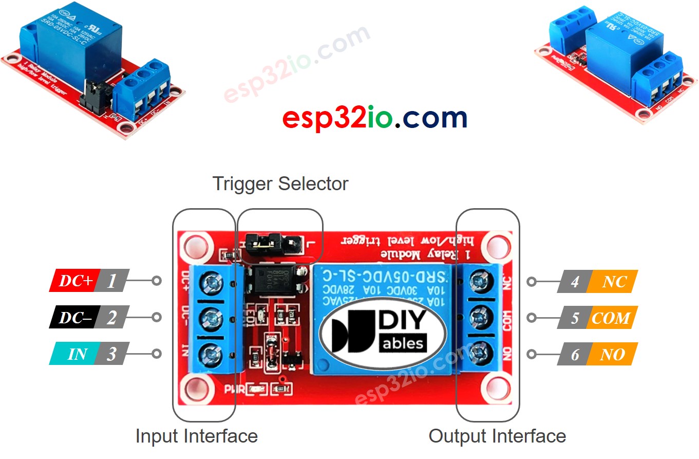
The relay pins can be categorized two groups: input (low voltage) and output (high voltage).
Normally, we do NOT use all high voltage pins. We usually use only two, depending on the operation mode we choose:
Additionally, if the relay supports both LOW and HIGH level triggers, there is usually a jumper to select one of two: LOW level trigger or HIGH level trigger.
※ NOTE THAT:
The pin order of the relay can be different between manufacturers. Please check the labels printed on the relay carefully!
How to Connect the high-voltage Device to Relay
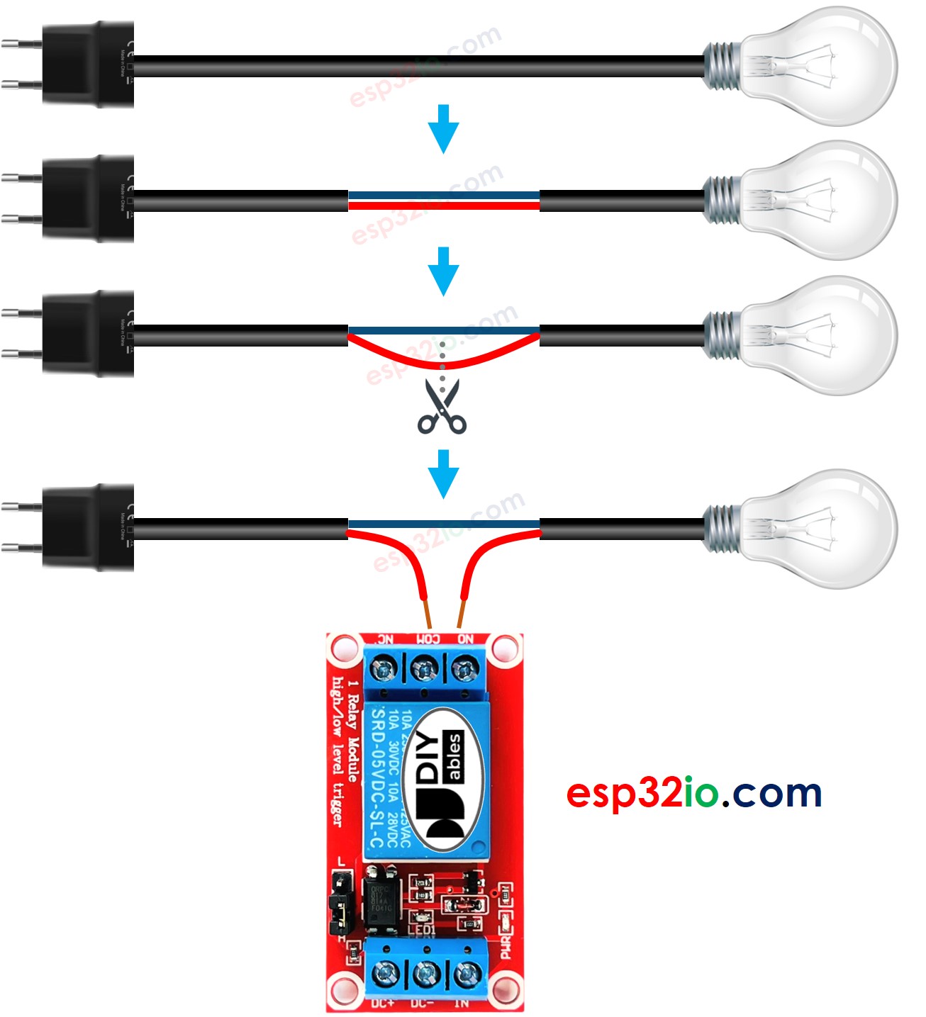
How Relay Works
There are several ways that a relay module can work, depending on our choices.
In the input side, we can choose one of the two below opposite input modes:
In the output side, we can choose one of the two below opposite output modes:
The “normally” means “if the IN pin is connected to LOW (0V)”.
Before going into detail, let's see some quick information:
The combination of the input modes mode and output modes modes creates many use cases. If you are a beginner, we recommend using HIGH level trigger mode and normally open mode
Because the LOW level trigger and HIGH level trigger mode work oppositely, The next will explain the HIGH level trigger mode in detail. The LOW level trigger works oppositely.
HIGH Level Trigger - Normally Open Mode
Connect the high-voltage device to the COM pin and NO pin. Just like a switch:
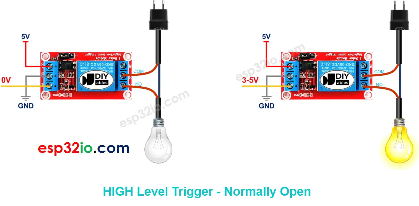
HIGH Level Trigger - Normally Closed Mode
Connect the the high-voltage device to the COM pin and NC pin. Just like a switch:
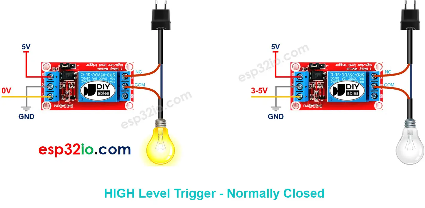
⇒ It depends on application.
Normally Open Mode vs Normally Closed Mode
The relay is just like a switch. The below table shows the difference between two modes in HIGH Level Trigger.
| Pins used | IN pin | Relay state | Device state | |
|---|---|---|---|---|
| Normally Open Mode | COM and NO pin | LOW | ⇒ open | ⇒ OFF |
| Normally Closed Mode | COM and NC pin | LOW | ⇒ closed | ⇒ ON |
| Normally Open Mode | COM and NO pin | HIGH | ⇒ closed | ⇒ ON |
| Normally Closed Mode | COM and NC pin | HIGH | ⇒ open | ⇒ OFF |
ESP32 - Relay
A high-voltage device can be controlled by ESP32 via a relay.
Controlling a relay is a piece of cake. We just need:
Wiring Diagram
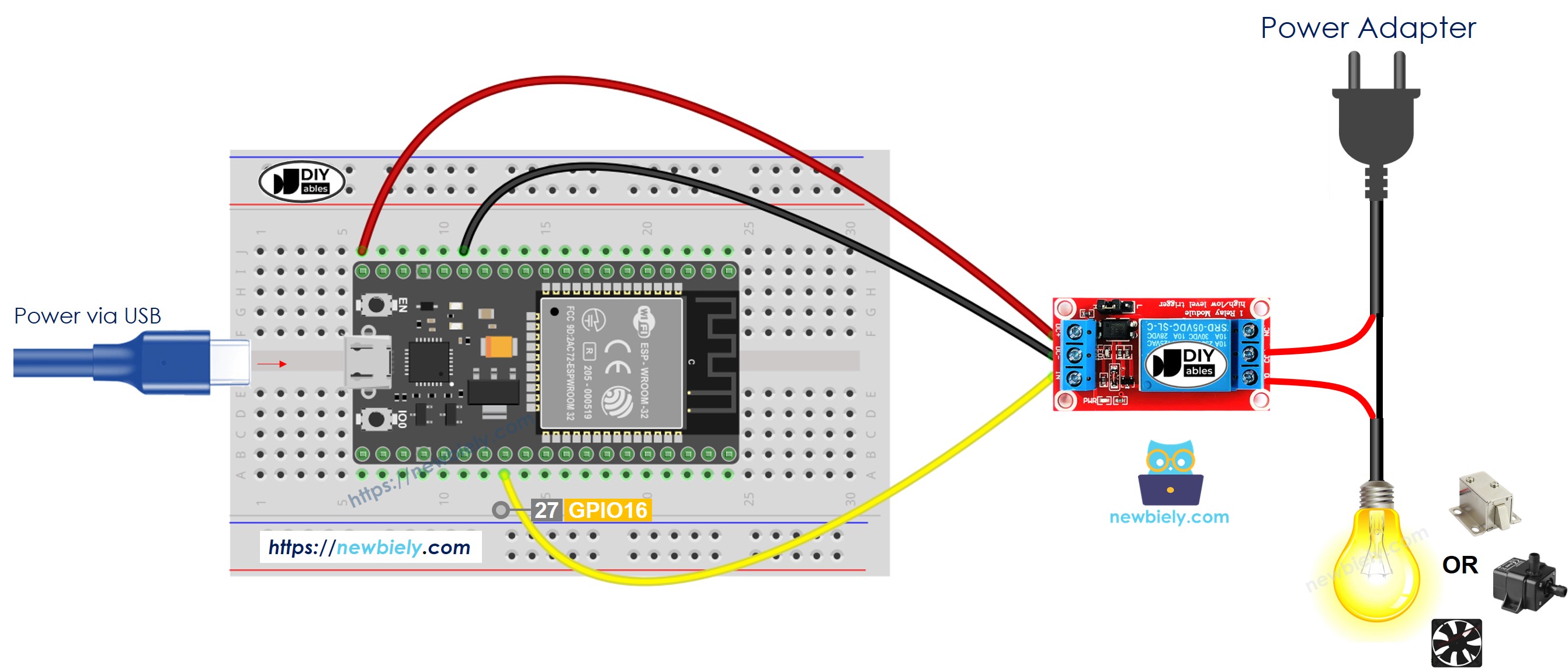
This image is created using Fritzing. Click to enlarge image
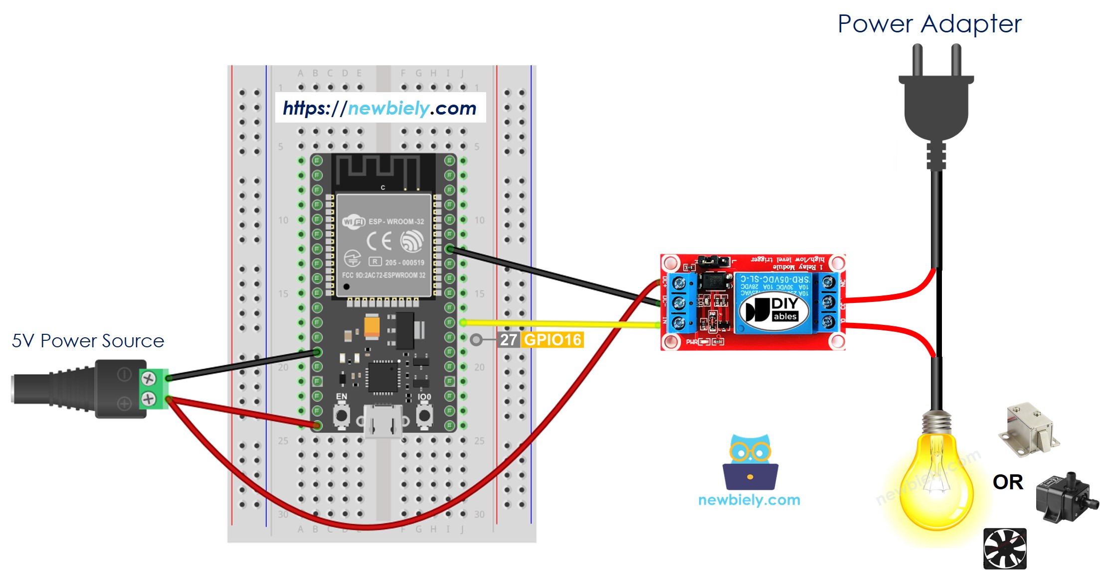
This image is created using Fritzing. Click to enlarge image
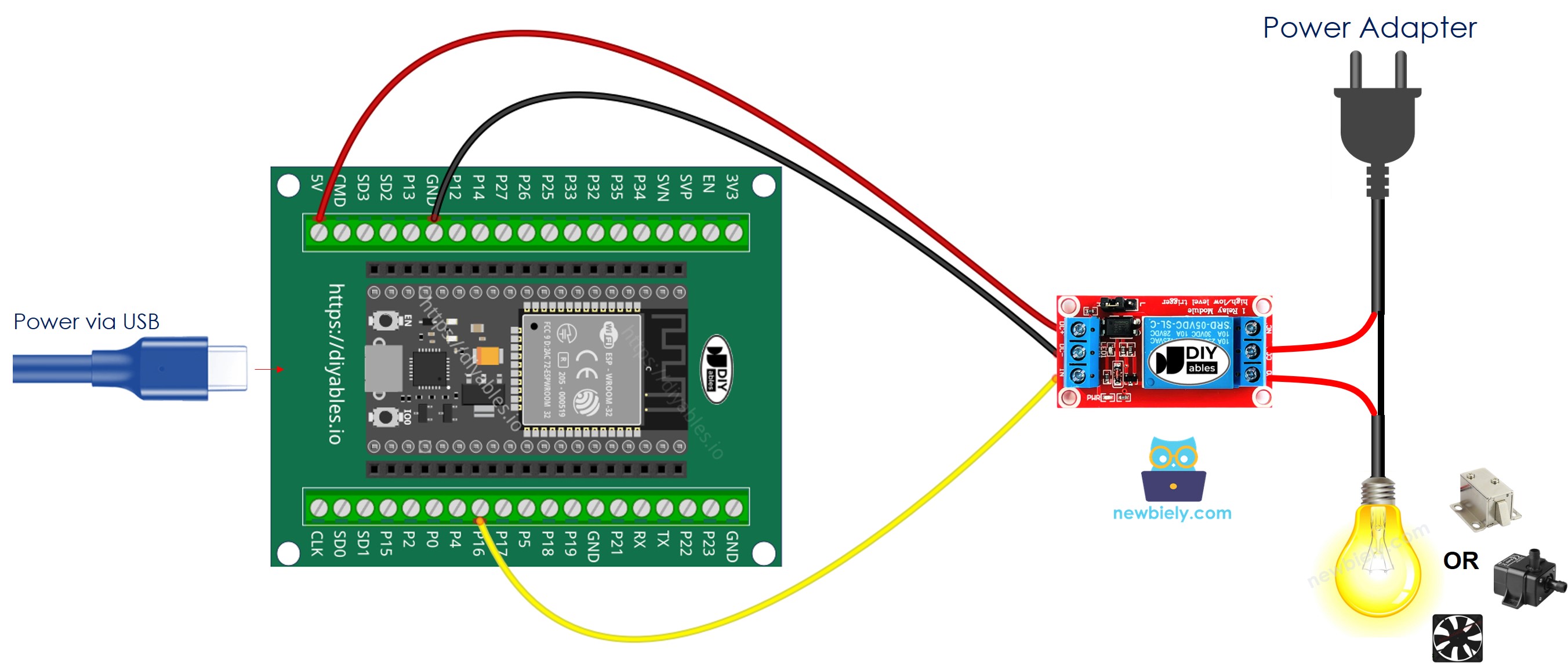
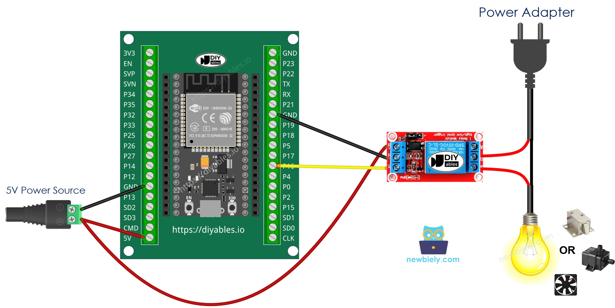
The wiring table between relay module and ESP32
| Relay Module | ESP32 |
|---|---|
| GND | → GND |
| VCC | → Vin (5V) |
| IN | → GPIO16 |
If you're unfamiliar with how to supply power to the ESP32 and other components, you can find guidance in the following tutorial: The best way to Power ESP32 and sensors/displays.
