ESP32 - Control LED via Web
In this tutorial, we are going to learn how to control an LED through a web interface using a browser on a PC or smartphone, utilizing the ESP32. In detail, , the ESP32 will be programmed to work as a web server. Let's assume that the IP address of the ESP32 is 192.168.0.2. Here are the details of how it works:
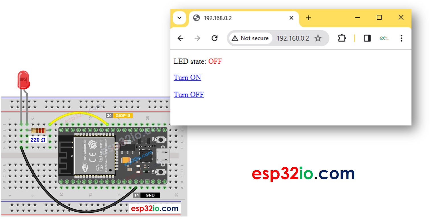
- When you enter 192.168.0.2 into the web browser, the browser sends a request to the ESP32, and the ESP32 responds with a web page that contains the on/off button for controlling the LED.
- Similarly, when you click the "Turn ON" button on the web page or type 192.168.0.2/led1/on into the web browser, the ESP32 turns on the LED and responds with the control web page.
- Likewise, when you click the "Turn OFF" button on the web page or type 192.168.0.2/led1/off into the web browser, the ESP32 turns off the LED and responds with the control web page.
We will learn through two example codes:
- HTML content is embedded into ESP32 code
- HTML content is separated from ESP32 code and put into a .h file
The tutorial offers the fundamentals that you can readily and innovatively customize to achieve the following:
- Controlling multiple LEDs through the web
- Redesigning the web user interface (UI)
Hardware Used In This Tutorial
Or you can buy the following kits:
| 1 | × | DIYables ESP32 Starter Kit (ESP32 included) | |
| 1 | × | DIYables Sensor Kit (18 sensors/displays) |
Buy Note: Want to make wiring easier? Try the LED Module. It already has a built-in resistor, so no extra parts needed!
Introduction to LED and ESP32
If you do not know about LED and ESP32 (pinout, how it works, how to program ...), learn about them in the following tutorials:
Wiring Diagram
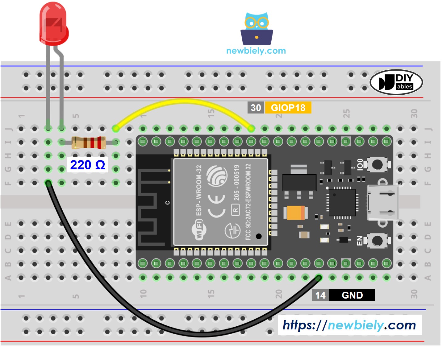
This image is created using Fritzing. Click to enlarge image
If you're unfamiliar with how to supply power to the ESP32 and other components, you can find guidance in the following tutorial: The best way to Power ESP32 and sensors/displays.
ESP32 Code - HTML content is embedded into ESP32 code
Quick Instructions
- If this is the first time you use ESP32, see how to setup environment for ESP32 on Arduino IDE.
- Do the wiring as above image.
- Connect the ESP32 board to your PC via a micro USB cable
- Open Arduino IDE on your PC.
- Select the right ESP32 board (e.g. ESP32 Dev Module) and COM port.
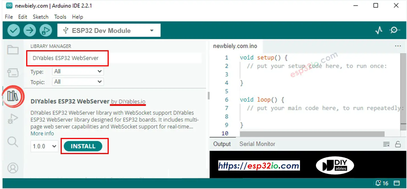
- Open the Library Manager by clicking on the Library Manager icon on the left navigation bar of Arduino IDE.
- Search “DIYables ESP32 WebServer”, then find the Web Server library created by DIYables.
- Click Install button to install the Web Server library.
- Copy the above code and open with Arduino IDE
- Change the wifi information (SSID and password) in the code to yours
- Click Upload button on Arduino IDE to upload code to ESP32
- Open the Serial Monitor
- See the result on Serial Monitor.
- You will see an IP address, for example: 192.168.0.2. This is the IP address of the ESP32 Web Server
- Open a web browser and enter one of the three formats below into the address bar:
- Kindly be aware that the IP address might vary. Please verify the current value on the Serial Monitor.
- You will also see the below output on Serial Monitor
- Check LED state
- You will see the web page of ESP32 board on the web browser as below
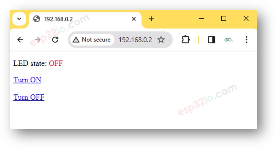
- You are now able to control the LED on/off via the web interface
ESP32 Code - HTML content is separated from ESP32 code
As a graphic web page contains a large amount of HTML content, embedding it into the ESP32 code as before becomes inconvenient. To address this, we need to separate the ESP32 code and the HTML code into different files:
- The ESP32 code will be placed in a .ino file.
- The HTML code (including HTML, CSS, and Javascript) will be placed in a .h file.
Quick Instructions
- Open Arduino IDE and create new sketch, Give it a name, for example, newbiely.com.ino
- Copy the below code and open with Arduino IDE
- Change the WiFi information (SSID and password) in the code to yours
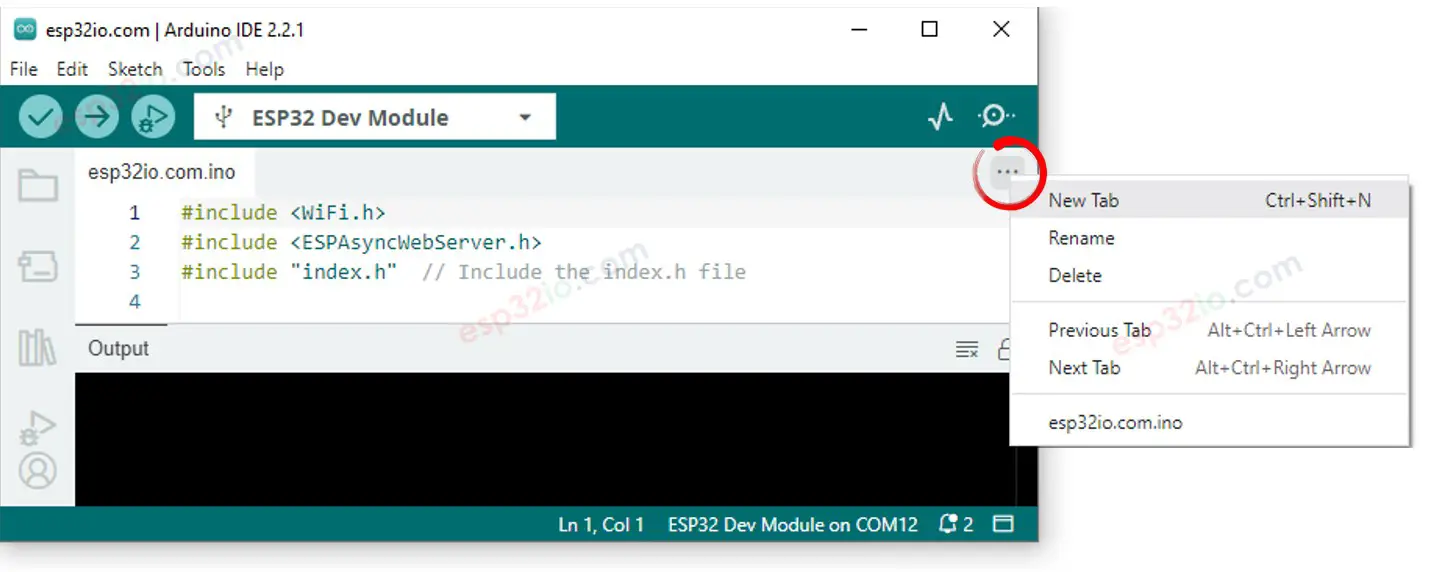
- Create the index.h file On Arduino IDE by:
- Either click on the button just below the serial monitor icon and choose New Tab, or use Ctrl+Shift+N keys.
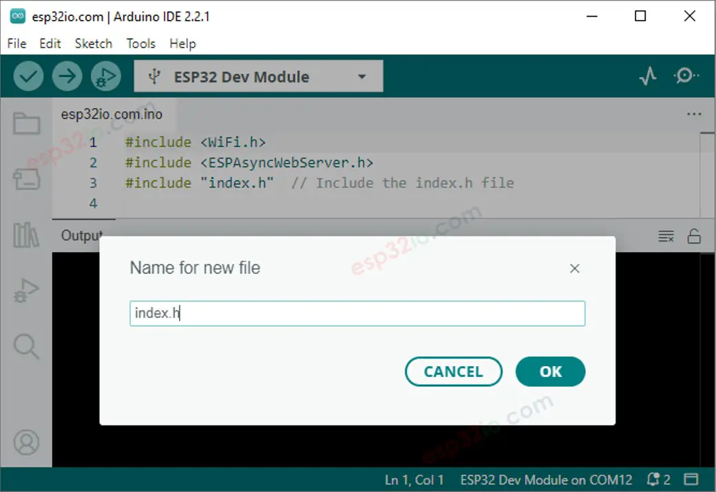
- Give the file's name index.h and click OK button
- Copy the below code and paste it to the index.h.
- Now you have the code in two files: newbiely.com.ino and index.h
- Click Upload button on Arduino IDE to upload code to ESP32
- Access the web page of ESP32 board via web browser on your PC or smartphone as before. You will see it similar to the previous code as below:
- If you modify the HTML content in the index.h and does not touch anything in newbiely.com.ino file, when you compile and upload code to ESP32, Arduino IDE will not update the HTML content.
- To make Arduino IDE update the HTML content in this case, make a change in the newbiely.com.ino file (e.g. adding empty line, add a comment....)
- Controlling multiple LEDs through the web
- Redesigning the web user interface (UI)
※ NOTE THAT:
You can readily and innovatively customize the above ocde to achieve the following: