ESP32 - TCS3200D/TCS230 Color Sensor
This guide walks you through connecting a TCS3200D/TCS230 color sensor to ESP32 for accurate RGB color detection and measurement. Learn how to calibrate the sensor and program the ESP32 to read color values from objects.
What you'll learn:
- Connecting the TCS3200D/TCS230 color sensor to ESP32
- Calibrating the sensor to compensate for environmental factors
- Writing ESP32 code to measure and output RGB values
Hardware Used In This Tutorial
Or you can buy the following kits:
| 1 | × | DIYables ESP32 Starter Kit (ESP32 included) | |
| 1 | × | DIYables Sensor Kit (18 sensors/displays) |
Introduction to TCS3200D/TCS230 Color Sensor
The TCS3200D/TCS230 employs a 64-photodiode matrix organized in an 8×8 configuration for color identification. This array comprises 16 photodiodes fitted with red optical filters, 16 with green filters, 16 with blue filters, and 16 without filters (clear). The sensor operates by selecting specific filter types and converting the detected light intensity into a frequency-modulated square wave output.
Most sensor modules feature integrated white LED illumination, which maintains measurement consistency by providing a controlled light source independent of ambient conditions.
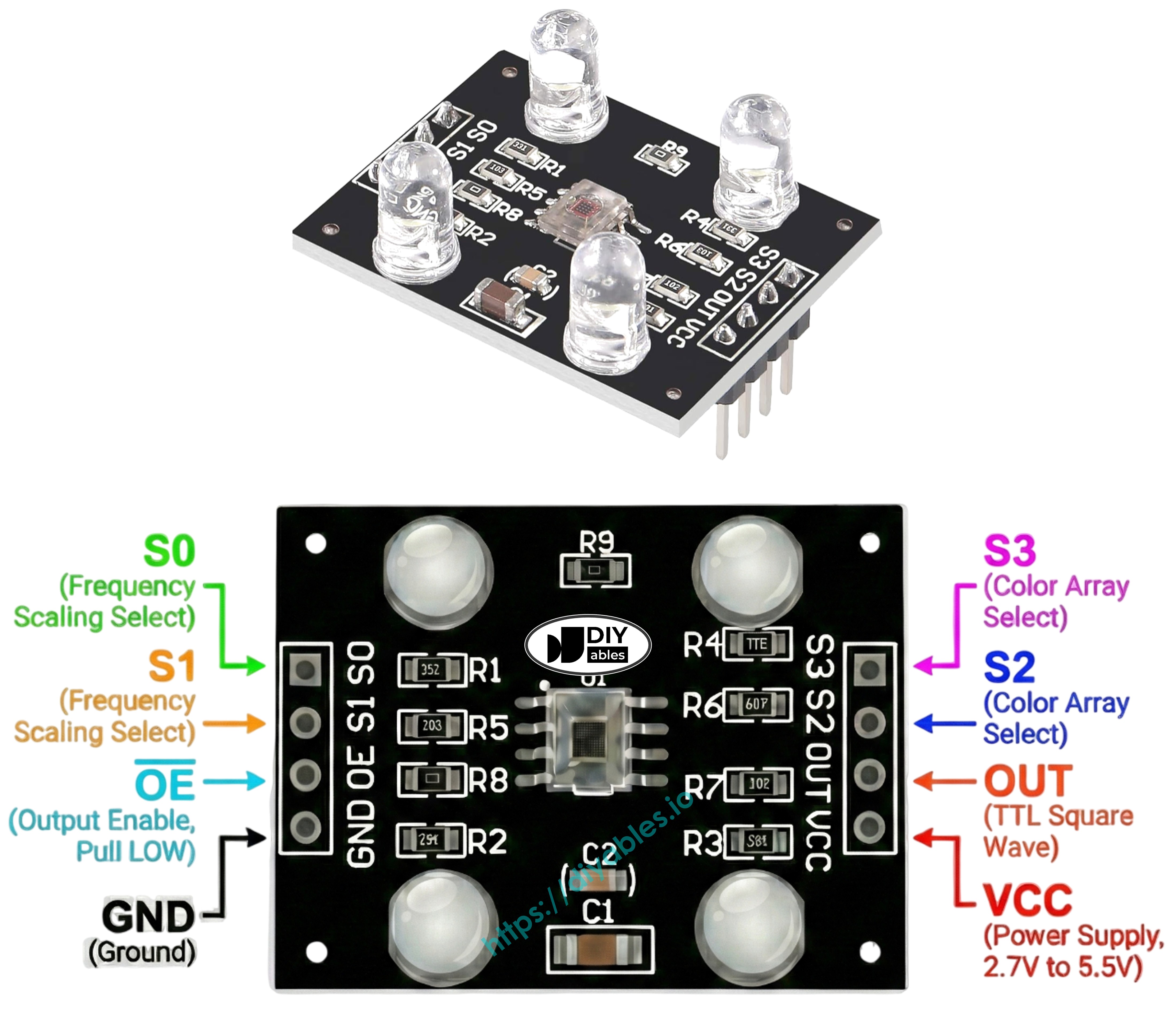
Pinout
The TCS3200D/TCS230 sensor module provides these connection points:
- VCC pin: Connect to 3.3V or 5V power supply.
- GND pin: Connect to ground (0V).
- S0, S1 pins: Output frequency scaling controls.
- S2, S3 pins: Color filter selectors.
- OUT pin: Square-wave frequency output signal.
- OE pin: Output enable (active LOW). Typically pre-wired to GND on commercial modules. If exposed, connect to GND.
How It Works
Sensor operation depends on two configurable parameters: active color filter and output signal strength. Two control pin pairs determine these settings:
S0/S1 pins configure output frequency scaling:
- S0=LOW, S1=LOW: Sensor powered down
- S0=LOW, S1=HIGH: Output at 2% of base frequency
- S0=HIGH, S1=LOW: Output at 20% of base frequency
- S0=HIGH, S1=HIGH: Output at 100% of base frequency
S2/S3 pins select the active color filter:
- S2=LOW, S3=LOW: Red filter engaged
- S2=LOW, S3=HIGH: Blue filter engaged
- S2=HIGH, S3=LOW: No filter (clear/unfiltered)
- S2=HIGH, S3=HIGH: Green filter engaged
The OUT pin produces frequency output between roughly 2 Hz and 500 kHz. Frequency magnitude correlates with light intensity—more light yields higher frequency. Using pulseIn() to measure pulse duration gives the inverse—lower pulse width indicates brighter illumination. After calibration, these measurements convert to standard 0-255 RGB values.
Optimizing Measurement Stability
- Position sensor 1-3 cm from target surface with consistent orientation.
- Enable built-in white LEDs for standardized illumination.
- Block external light sources to reduce measurement variability.
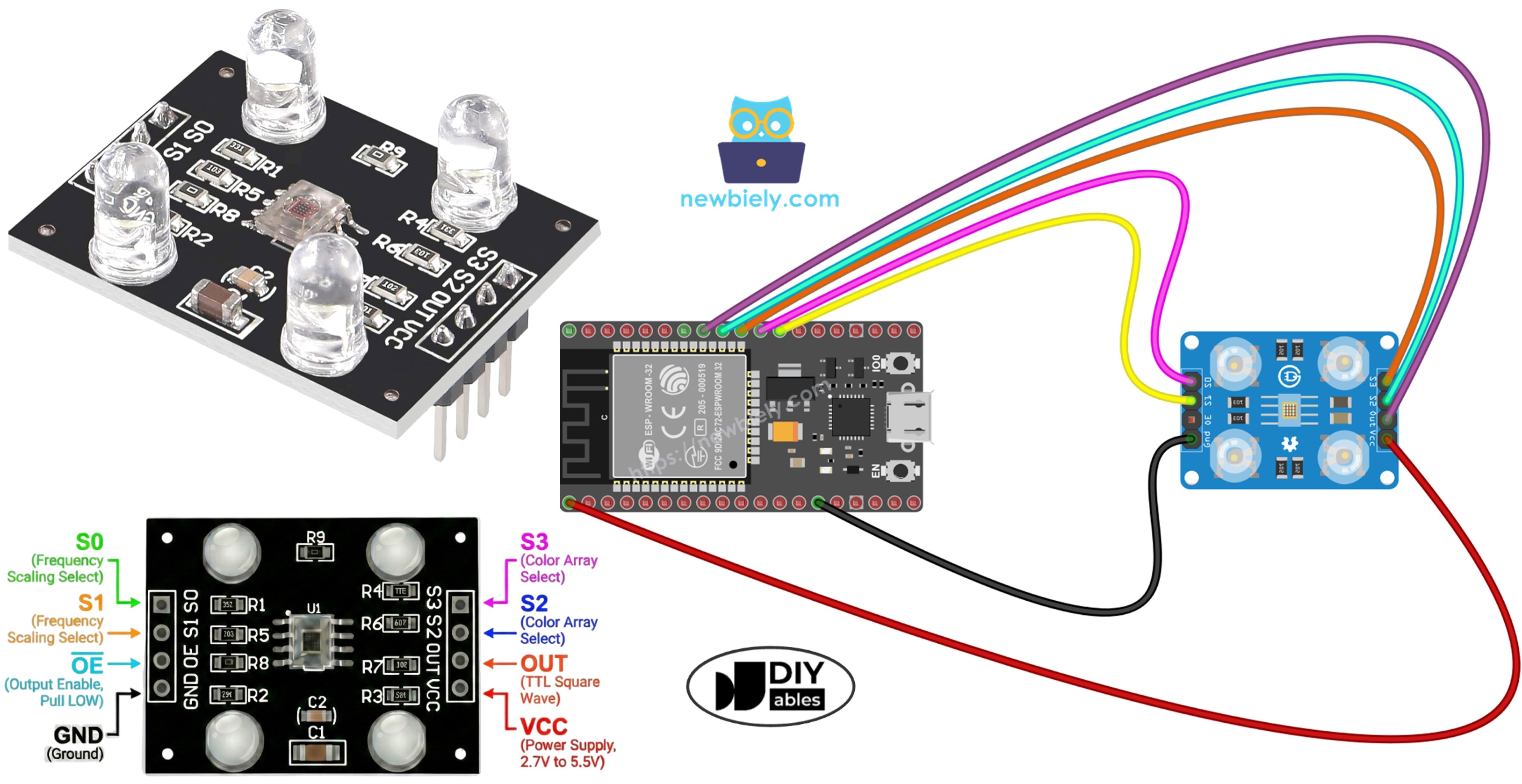
Wiring Diagram
ESP32 to TCS3200 color sensor connection layout:
| TCS3200 Color Sensor | ESP32 |
|---|---|
| VCC | 3.3V |
| GND | GND |
| S0 | GPIO 17 |
| S1 | GPIO 16 |
| S2 | GPIO 18 |
| S3 | GPIO 5 |
| OUT | GPIO 19 |
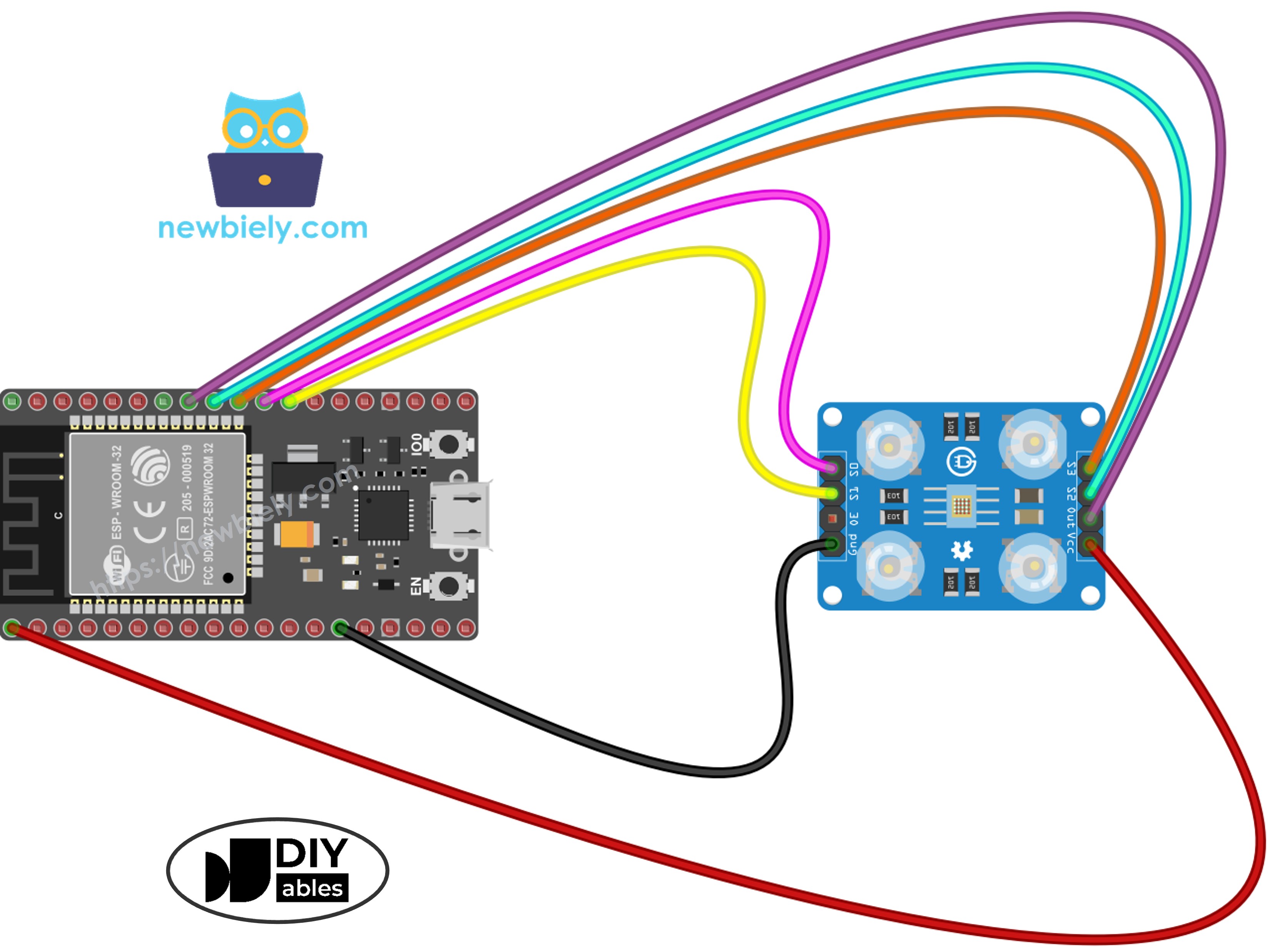
This image is created using Fritzing. Click to enlarge image
If you're unfamiliar with how to supply power to the ESP32 and other components, you can find guidance in the following tutorial: The best way to Power ESP32 and sensors/displays.
ESP32 Code - Sensor Calibration via Pulse Width
Calibration compensates for environmental variables affecting raw sensor readings: LED brightness variations, object distance, surface reflectivity differences, and ambient lighting conditions. These factors introduce measurement errors that must be quantified. The calibration process records minimum and maximum pulse widths for each color channel, creating boundaries for accurate 0–255 RGB mapping in your specific environment.
Quick Instructions
- If this is the first time you use ESP32, see how to setup environment for ESP32 on Arduino IDE.
- Copy the calibration code into Arduino IDE
- Click the Upload button on Arduino IDE to upload code to ESP32
- Open Serial Monitor (set baud rate to 9600)
- Point sensor at different colored objects: white paper, black surface, and various colors
- Monitor the Min/Max values as they auto-update
- After values stabilize (10-20 seconds), note down all six calibration numbers
Example calibration results from the output:
- RedMin = 42, redMax = 210
- GreenMin = 55, greenMax = 185
- BlueMin = 60, blueMax = 172
ESP32 Code - Reading RGB Color Values
Quick Instructions
- Find the calibration constants at the top of the code:
- Replace all six zeros with your actual calibration values. For example (using redMin = 42, redMax = 210, greenMin = 55, greenMax = 185, blueMin = 60, blueMax = 172):
- Copy the above code and open with Arduino IDE
- Click Upload button on Arduino IDE to upload code to ESP32
- Place a colored object in front of the sensor
- See the result on Serial Monitor
Output now displays standard 0-255 RGB values. Shorter pulse widths (brighter illumination) yield higher RGB numbers; longer pulse widths (dimmer conditions) produce lower values.
Project Applications
With functional RGB reading capability, explore these project possibilities:
- Automated color sorting: Categorize items by hue (red, green, blue identification)
- Color comparison system: Verify color matching between objects
- Chromatic line tracking: Build robots that follow colored paths
- Manufacturing quality check: Identify defective units through color deviation
- Color-triggered response: Activate buzzers or indicators upon detecting specific colors
Video Tutorial
Making video is a time-consuming work. If the video tutorial is necessary for your learning, please let us know by subscribing to our YouTube channel , If the demand for video is high, we will make the video tutorial.