ESP32 - Flame Sensor
The flame sensor can detect and measure the infrared light coming from a flame. It's useful for spotting fires and is also known as an infrared flame sensor or fire sensor. This sensor provides two types of information: one is like a simple switch (either on or off), and the other is analog signal showing the strength of the flame.
In this tutorial, we'll learn how to use an ESP32 with a flame sensor to detect flames. Specifically, we'll cover these steps:
- Connecting the flame sensor to an ESP32.
- Programming the ESP32 to recognize fires by reading the on/off signal from the flame sensor.
- Programming the ESP32 to measure the flame's strength by reading the analog signal from the flame sensor.
Afterward, you can modify the code to activate a warning horn when the fire is detected.
This tutorial shows how to program the ESP32 using the Arduino language (C/C++) via the Arduino IDE. If you’d like to learn how to program the ESP32 with MicroPython, visit this ESP32 MicroPython - Flame Sensor tutorial.
Hardware Used In This Tutorial
Or you can buy the following kits:
| 1 | × | DIYables ESP32 Starter Kit (ESP32 included) | |
| 1 | × | DIYables Sensor Kit (18 sensors/displays) |
Introduction to Flame Sensor
The infrared flame sensor can detect a flame or check how much infrared light the flame gives off. So, it helps us spot fires. This sensor offers two choices using a digital output pin and an analog output pin.
These sensors are designed to catch a certain types of infrared light emitted by flames while ignoring other types, like the heat from people or indoor lights. But like any sensor, they have their limits, and sometimes they might make mistakes, either saying there's a fire when there isn't (false positive) or missing a fire when it's there (false negative).
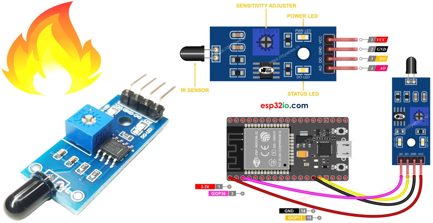
Pinout
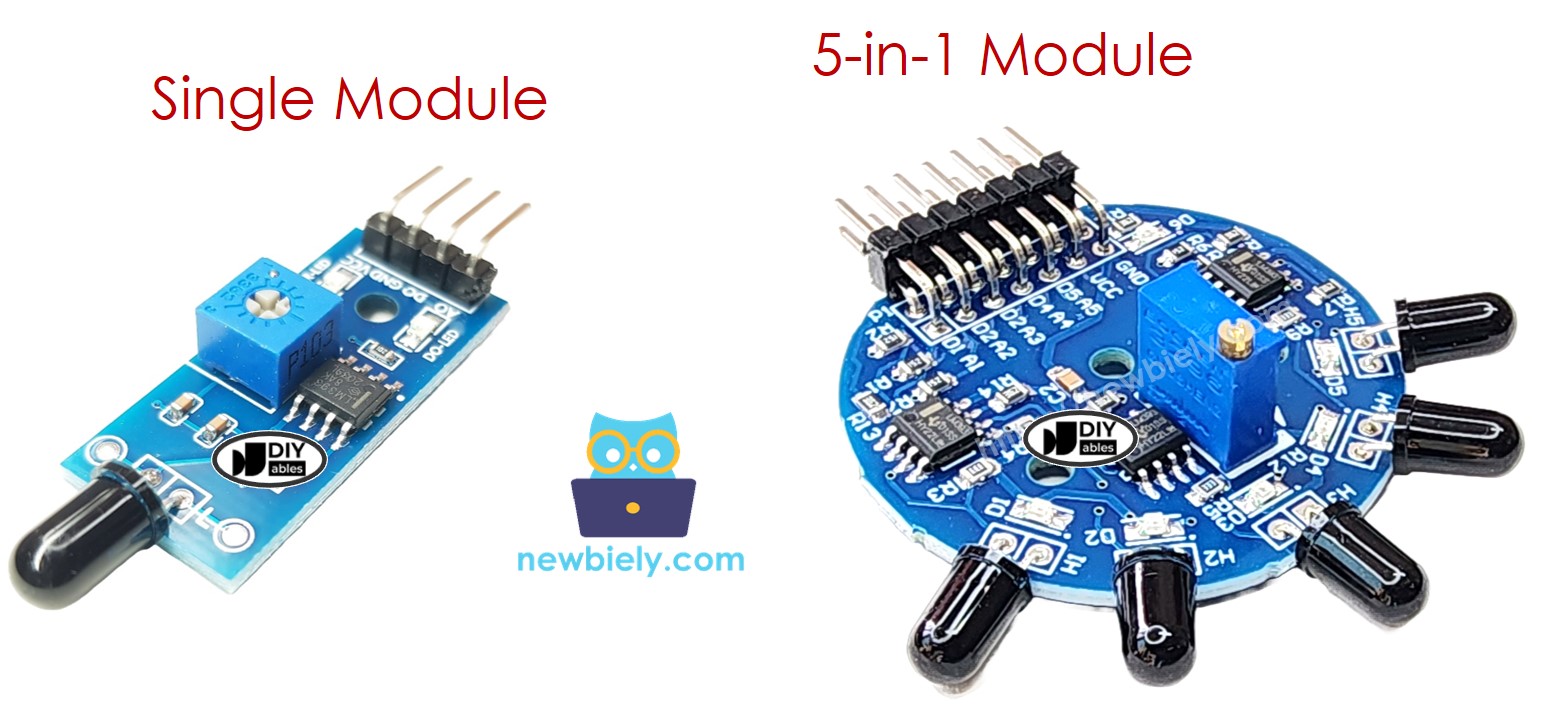
There are two types of flame sensor modules available:
A single flame sensor includes four pins:
- VCC pin: It needs to be connected to VCC (3.3V to 5V).
- GND pin: It needs to be connected to GND (0V).
- DO pin: It is a digital output pin. It is HIGH if the flame is not detected and LOW if detected. The threshold value for flame detection can be adjusted using a built-in potentiometer.
- AO pin: It is an analog output pin. The output value decreases as the infraed level is decreased, and it increases as infraed level is increased.
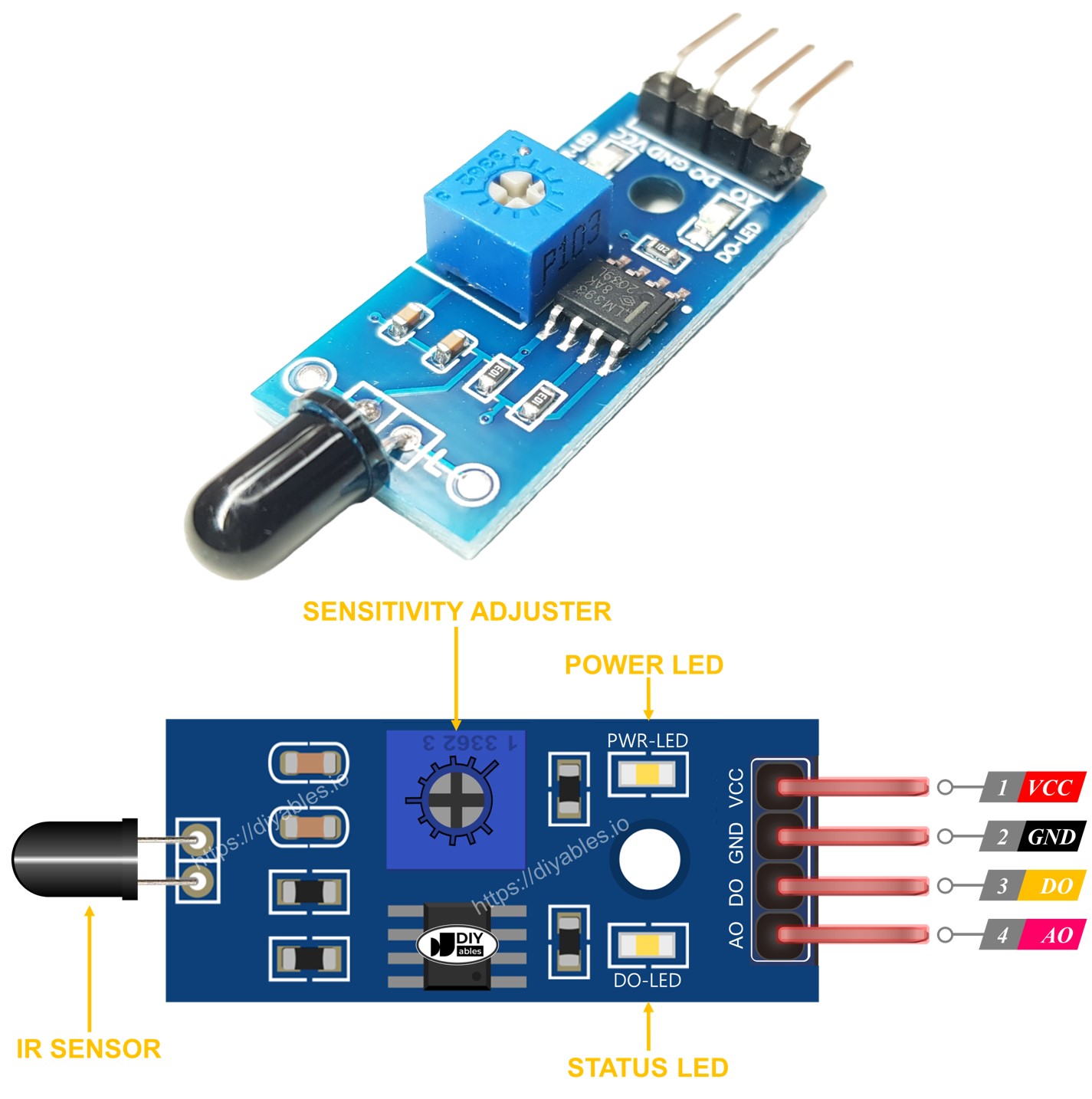
Furthermore, it has two LED indicators:
- One PWR-LED indicator for power.
- One DO-LED indicator for the flame state on the DO pin: it is on when flame is present.
The 5-in-1 flame sensor module combines five individual flame sensors on a single PCB. The sensors share a common potentiometer, VCC, and GND connections, while each sensor has its own independent DO (Digital Output) and AI (Analog Input) pins.
How It Works
For the DO pin:
- The module has a built-in potentiometer for setting the infrared threshold (sensitivity).
- When the infrared intensity is above the threshold value, the flame is detected, the output pin of the sensor is LOW, and the DO-LED is on.
- When the infrared intensity is below the threshold value, the flame is NOT detected, the output pin of the sensor is HIGH, and the DO-LED is off.
For the AO pin:
- The higher the infrared intensity in the surrounding environment, the higher the value read from the AO pin.
- The lower the infrared intensity in the surrounding environment, the lower the value read from the AO pin.
Note that the potentiometer does not affect the value on the AO pin.
Wiring Diagram
Since the flame sensor module has two outputs, you can choose to use one or both of them, depending on what you need.
- How to connect ESP32 and flame sensor using breadboard
The flame sensor module provides two output options. You can use one or both based on what you need.
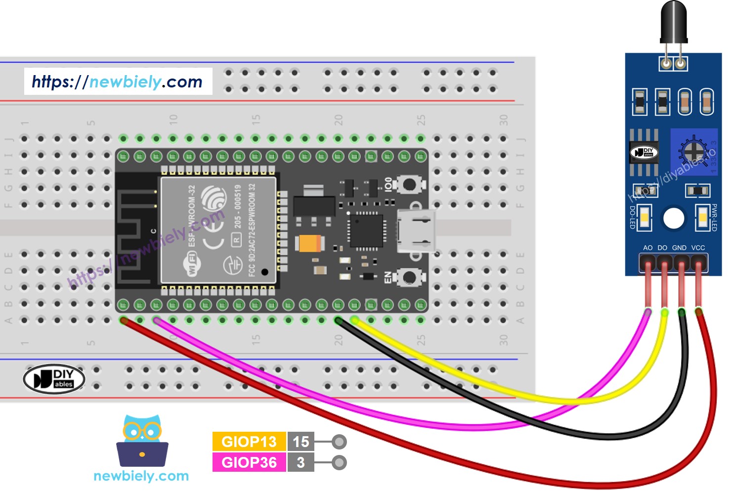
This image is created using Fritzing. Click to enlarge image
- How to connect ESP32 and flame sensor using screw terminal block breakout board
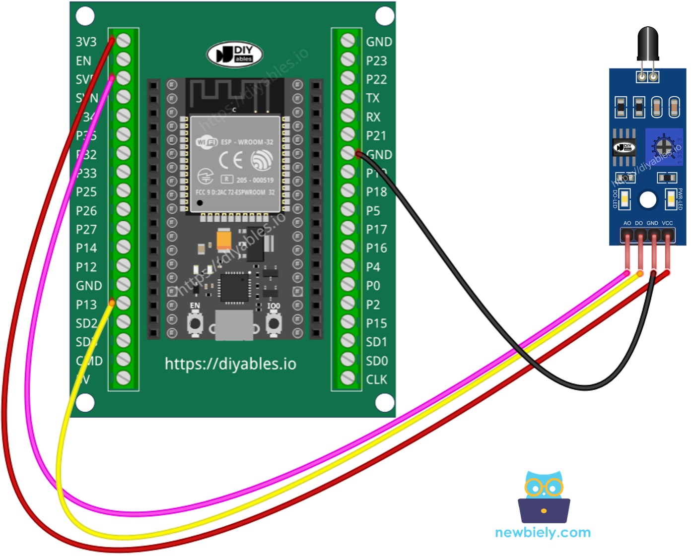
If you're unfamiliar with how to supply power to the ESP32 and other components, you can find guidance in the following tutorial: The best way to Power ESP32 and sensors/displays.
ESP32 Code - Read value from DO pin
Quick Instructions
- If this is the first time you use ESP32, see how to setup environment for ESP32 on Arduino IDE.
- Copy the above code and open with Arduino IDE
- Click Upload button on Arduino IDE to upload code to ESP32
- Direct the flame sensor to a flame.
- See the result on Serial Monitor.
Please keep in mind that if you notice the LED status remaining on constantly or off even when the sensor faces to a flame, you can adjust the potentiometer to fine-tune the sensitivity of the sensor.
ESP32 Code - Read value from AO pin
Quick Instructions
- Copy the above code and open with Arduino IDE
- Click Upload button on Arduino IDE to upload code to ESP32
- Direct the flame sensor to a flame.
- See the result on Serial Monitor.
※ NOTE THAT:
This tutorial uses the analogRead() function to read values from an ADC (Analog-to-Digital Converter) connected to a flame sensor. The ESP32 ADC is good for projects that do NOT need high accuracy. However, for projects that need precise measurements, please note:
- The ESP32 ADC is not perfectly accurate and might need calibration for correct results. Each ESP32 board can be a bit different, so you need to calibrate the ADC for each individual board.
- Calibration can be difficult, especially for beginners, and might not always give the exact results you want.
For projects that need high precision, consider using an external ADC (e.g ADS1115) with the ESP32 or using an Arduino, which has a more reliable ADC. If you still want to calibrate the ESP32 ADC, refer to ESP32 ADC Calibration Driver
Video Tutorial
Making video is a time-consuming work. If the video tutorial is necessary for your learning, please let us know by subscribing to our YouTube channel , If the demand for video is high, we will make the video tutorial.