ESP32 - 4-Channel Relay Module
This tutorial provides step-by-step instructions on utilizing an ESP32 to control a 4-channel relay module. It covers the following aspects in detail:
- Understanding the pinout configuration of a 4-channel relay module
- Establishing the connections between an ESP32 and the 4-channel relay module
- Programming the ESP32 to effectively control the 4-channel relay module
When it comes to managing four high-voltage devices such as pumps, fans, or actuators, we have two choices. We can either go with multiple relay modules or opt for a simpler approach. The simpler option is to use a 4-channel relay module, which is a single board equipped with four integrated relays. This streamlines the setup process, making it more convenient to control all the devices effectively.
Hardware Used In This Tutorial
Or you can buy the following kits:
| 1 | × | DIYables ESP32 Starter Kit (ESP32 included) | |
| 1 | × | DIYables Sensor Kit (18 sensors/displays) |
Introduction to 4-Channel Relay Module
The 4-Channel Relay Module Pinout
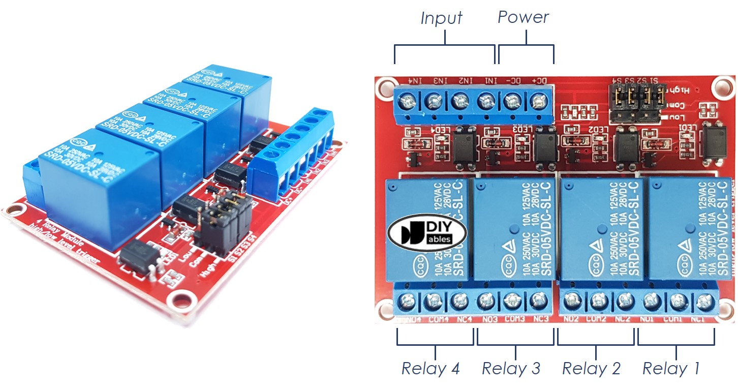
A 4-channel relay module has the following pins:
- Power pins for relay boards
- DC+: connect this pin to the 5V pin of a power supply
- DC-: connect this pin to the GND pin of the power supply and also to the GND pin of an ESP32
- Signal pins:
- IN1: this pin receives the control signal from an ESP32 to control relay 1 on the module
- IN2: this pin receives the control signal from an ESP32 to control relay 2 on the module
- IN3: this pin receives the control signal from an ESP32 to control relay 3 on the module
- IN4: this pin receives the control signal from an ESP32 to control relay 4 on the module
- Output pins: NCx (normally closed pin), NOx (normally open pin), COMx (common pin),
- NC1, NO1, COM1: These pins connect to a high-voltage device that is controlled by relay 1
- NC2, NO2, COM2: These pins connect to a high-voltage device that is controlled by relay 2
- NC3, NO3, COM3: These pins connect to a high-voltage device that is controlled by relay 3
- NC4, NO4, COM4: These pins connect to a high-voltage device that is controlled by relay 4
To learn about connecting a relay to high-voltage devices and understanding the distinctions between normally closed and normally open, check out the ESP32 - Relay tutorial.
Additionally, the tutorial covers the 4 jumpers available on the relay module, which enable you to individually select between low trigger and high trigger settings for each relay.
Wiring Diagram
It is important to note that the 4-channel relay module consumes a significant amount of power. Therefore, it is strongly advised against powering it directly from the 5V pin of the ESP32. Instead, it is recommended to utilize an external 5V power source specifically for the relay module. This precaution ensures optimal performance and prevents potential issues that may arise from insufficient power supply.
Therefore, we must use three power sources:
- A 5V power adapter for the ESP32
- A 5V power adapter for the 4-channel relay module
- A higher-voltage power adapter (12VDC, 24VDC, 48VDC, 220AC...) for the items that are managed by the 4-channel relay module
- A wiring diagram with the three power sources. The power supply for the ESP32 (not included in the image) can be either via USB cable or power jack.
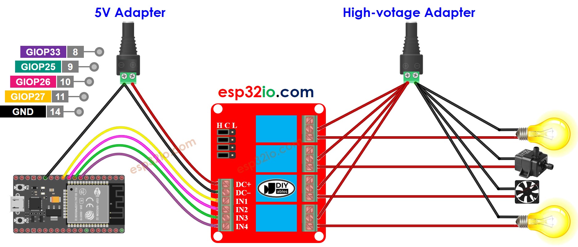
This image is created using Fritzing. Click to enlarge image
- We can decrease the amount of power adapters by utilizing one 5V power source for both the ESP32 and the 4-channel relay module.
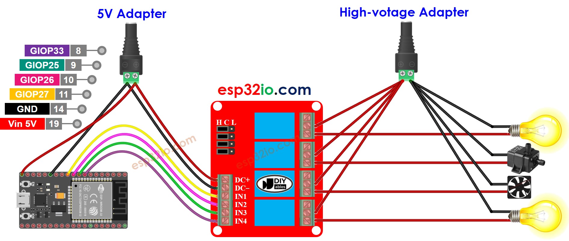
This image is created using Fritzing. Click to enlarge image
※ NOTE THAT:
If the four devices that are managed by a 4-channel relay module have the same voltage, then one high-voltage power adapter can be used for all of them. However, if the voltage is different for each device, then separate high-voltage power adapters must be used.
If you're unfamiliar with how to supply power to the ESP32 and other components, you can find guidance in the following tutorial: The best way to Power ESP32 and sensors/displays.
How To Program For 4-Channel Relay Module
- Sets the ESP32 pin to digital output mode with the pinMode() function.
- Manipulate the relay's state with the digitalWrite() function.
ESP32 Code
Quick Instructions
To get started with ESP32 on Arduino IDE, follow these steps:
- Check out the how to setup environment for ESP32 on Arduino IDE tutorial if this is your first time using ESP32.
- Wire the components as shown in the diagram.
- Connect the ESP32 board to your computer using a USB cable.
- Open Arduino IDE on your computer.
- Choose the correct ESP32 board, such as (e.g. NodeMCU 1.0 (ESP-12E Module)), and its respective COM port.
- Copy the code and open it with the Arduino IDE.
- Click the Upload button in the IDE to send the code to the ESP32.
- Listen for the click sound of the relays.
- Check the Serial Monitor to observe the result.
Video Tutorial
Making video is a time-consuming work. If the video tutorial is necessary for your learning, please let us know by subscribing to our YouTube channel , If the demand for video is high, we will make the video tutorial.