ESP32 - Keypad 1x4
In this guide, we will discover how to use a 1x4 keypad with an ESP32. We will cover:
- How to connect a 1x4 keypad with an ESP32.
- How to program ESP32 to detect which keys are pressed on a 1x4 keypad.
Hardware Used In This Tutorial
Or you can buy the following kits:
| 1 | × | DIYables ESP32 Starter Kit (ESP32 included) | |
| 1 | × | DIYables Sensor Kit (18 sensors/displays) |
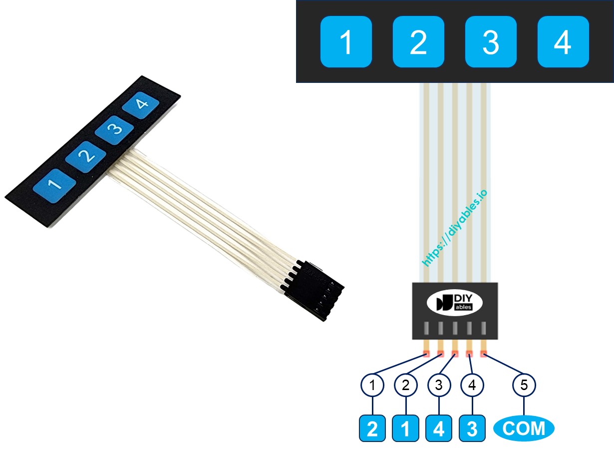
Introduction to Keypad 1x4
A 1x4 keypad has four membrane buttons lined up in a row. It is often used to let users enter data, like passwords, navigate menus, or control devices.
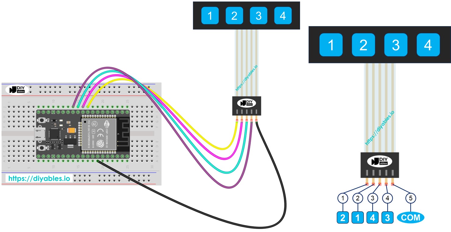
Pinout
The 1x4 keypad has 5 pins. The arrangement of these pins does not match the order of the key labels.
- Pin 1: links with key 2
- Pin 2: links with key 1
- Pin 3: links with key 4
- Pin 4: links with key 3
- Pin 5: connects to all keys and is a common pin
Wiring Diagram
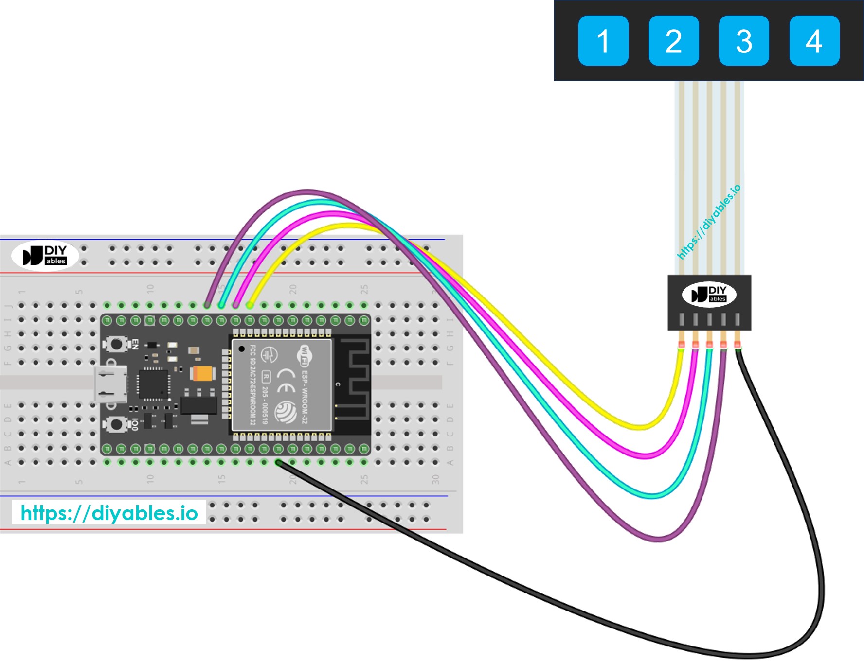
This image is created using Fritzing. Click to enlarge image
If you're unfamiliar with how to supply power to the ESP32 and other components, you can find guidance in the following tutorial: The best way to Power ESP32 and sensors/displays.
ESP32 Code
Each key on the 1x4 keypad works like a button. This lets us use the digitalRead() function to check each key's status. But, just like other buttons, these keys can 'bounce'. This means a single press might be detected as many presses. To fix this, we must debounce each key. Doing this for four keys without interrupting other code parts can be tough. Luckily, the ezButton library makes it easier.
Quick Instructions
- If this is the first time you use ESP32, see how to setup environment for ESP32 on Arduino IDE.
- Connect the ESP32 to the 1x4 keypad.
- Connect the ESP32 board to your PC via a USB cable
- Open Arduino IDE on your PC.
- Select the right ESP32 board (e.g. ESP32 Dev Module) and COM port.
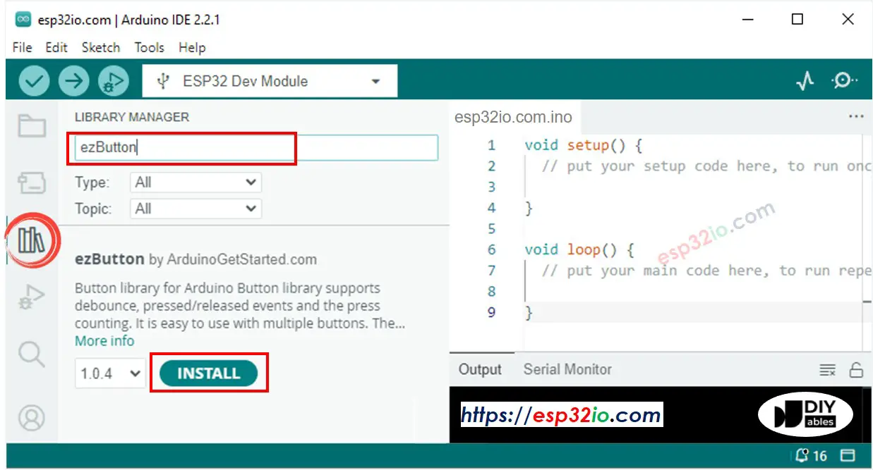
- Navigate to the Libraries icon on the left bar of the Arduino IDE.
- Search “ezButton”, then find the button library by ArduinoGetStarted.com
- Click Install button to install ezButton library.
- Copy the code and open it in Arduino IDE
- Click the Upload button in Arduino IDE to send the code to ESP32
- Open Serial Monitor
- Press each key on the 1x4 keypad
- Check the results in Serial Monitor