ESP32 - DIP Switch
DIP (Dual In-line Package) switches are commonly used in electronics for configuration purposes, such as setting device addresses, enabling or disabling features, etc. In this tutorial, we are going to learn how to use the DIP switch with ESP32. In detail, we will learn:
- What is DIP switch and how it works
- How to connect the DIP switch to ESP32
- How to program ESP32 to read the ON/OFF state of DIP switch
- How to program ESP32 to read the integer number set by DIP switch
DIP (Dual In-line Package) switches are frequently employed in electronics for configuration purposes, such as setting device addresses, activating or deactivating features, and more. In this tutorial, we'll explore the utilization of the DIP switch with ESP32. Specifically, we'll cover the following topics:
- Understanding what a DIP switch is and its working principles.
- Connecting the DIP switch to the ESP32.
- Programming the ESP32 to detect the ON/OFF state of the DIP switch.
- Programming the ESP32 to interpret the integer value set by the DIP switch.
Hardware Used In This Tutorial
Or you can buy the following kits:
| 1 | × | DIYables ESP32 Starter Kit (ESP32 included) | |
| 1 | × | DIYables Sensor Kit (18 sensors/displays) |
Introduction to DIP Switch
DIP switches serve as a fundamental components for device configuration, enabling users to adjust parameters like device addresses, communication settings, security codes, operation modes, and system preferences across various industries and applications.
A DIP switch comprises multiple small slide switches grouped together, with each switch referred to as a "position". DIP switches come in various types determined by the number of positions they offer. Options include 2-position, 4-position, 5-position, 6-position, 8-position, and 10-position DIP switches...
Each position on a DIP switch corresponds to a bit of a configurable number. By toggling the positions between ON and OFF, users can set the desired numeric value. This flexibility allows for precise configuration of parameters according to specific requirements.
Pinout
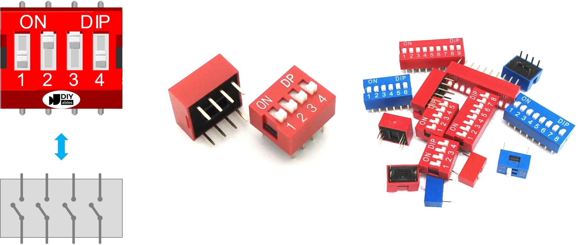
A DIP switch is composed of dual rows of pins, with the number of pins in each row matching the available switch positions. For instance, a 4-position DIP switch contains a total of 8 pins, evenly distributed with 4 pins on each side. Within the DIP switch structure, every pair of opposing pins forms a slide switch. It's important to note that distinguishing between pins on the two sides isn't required as they are interchangeable.
How It Works
In DIP switches, when a switch is in the ON position, it indicates that the switch is closed, establishing an electrical connection that allows current to flow through it.
Conversely, when a switch is in the OFF position, it means that the switch is open. In this state, the electrical connection is interrupted, preventing current from flowing through the switch.
To clarify:
- ON position: Forms a closed circuit, enabling current flow.
- OFF position: Results in an open circuit, blocking current flow.
When connecting one side of the switch to GND and the other to an ESP32 pin, and configuring the ESP32 pin as a pull-up digital input, the following table illustrates the relationship between the switch position and the values read from the ESP32:
| DIP switch position | Binary representation | Circuit state | ESP32 pin state |
|---|---|---|---|
| ON | 1 | CLOSED | LOW |
| OFF | 0 | OPEN | HIGH |
In the next parts, we will use 4-position DIP switch for example. You can easily to adapt for 2-position DIP switches, 3-position DIP switches, 5-position DIP switches, 6-position DIP switches, 8-position DIP switches, and 10-position DIP switches...
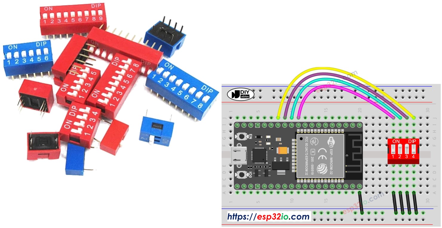
Wiring Diagram
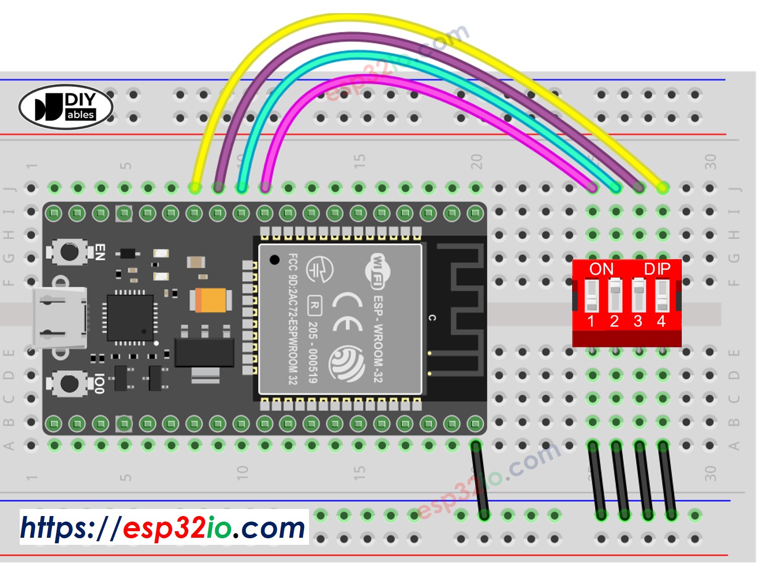
This image is created using Fritzing. Click to enlarge image
If you're unfamiliar with how to supply power to the ESP32 and other components, you can find guidance in the following tutorial: The best way to Power ESP32 and sensors/displays.
ESP32 Code - DIP Switch
We will learn through two pieces of code:
- Reading the ON/OFF state of individual position on the DIP switch.
- Encoding the positions into a number.
ESP32 code - Reading the ON/OFF state of the DIP switch
Quick Instructions
- If this is the first time you use ESP32, see how to setup environment for ESP32 on Arduino IDE.
- Do the wiring as above image.
- Connect the ESP32 board to your PC via a micro USB cable
- Open Arduino IDE on your PC.
- Select the right ESP32 board (e.g. ESP32 Dev Module) and COM port.
- Do wiring as above wiring diagram
- Connect ESP32 to PC via USB cable
- Open Arduino IDE
- Select the right board and port
- Click Upload button on Arduino IDE to upload code to ESP32
- Switch each position on the DIP Switch to ON one by one.
- See the result on Serial Monitor.
ESP32 code - Encoding the states of DIP switch into a number
Quick Instructions
- If this is the first time you use ESP32, see how to setup environment for ESP32 on Arduino IDE.
- Do the wiring as above image.
- Connect the ESP32 board to your PC via a micro USB cable
- Open Arduino IDE on your PC.
- Select the right ESP32 board (e.g. ESP32 Dev Module) and COM port.
- Upload the above code to ESP32
- Switch each position on the DIP switch to ON one by one.
- See the result on Serial Monitor, it look like below.
Please note that the value depends on positions of each slide switches. The below table shows the mapping between ON/OFF position and the integer value for 4-position DIP switch:
| Position-1 | Position-2 | Position-3 | Position-4 | Binary Value | Decimal Value |
|---|---|---|---|---|---|
| OFF | OFF | OFF | OFF | 0000 | 0 |
| OFF | OFF | OFF | ON | 0001 | 1 |
| OFF | OFF | ON | OFF | 0010 | 2 |
| OFF | OFF | ON | ON | 0011 | 3 |
| OFF | ON | OFF | OFF | 0100 | 4 |
| OFF | ON | OFF | ON | 0101 | 5 |
| OFF | ON | ON | OFF | 0110 | 6 |
| OFF | ON | ON | ON | 0111 | 7 |
| ON | OFF | OFF | OFF | 1000 | 8 |
| ON | OFF | OFF | ON | 1001 | 9 |
| ON | OFF | ON | OFF | 1010 | 10 |
| ON | OFF | ON | ON | 1011 | 11 |
| ON | ON | OFF | OFF | 1100 | 12 |
| ON | ON | OFF | ON | 1101 | 13 |
| ON | ON | ON | OFF | 1110 | 14 |
| ON | ON | ON | ON | 1111 | 15 |
Video Tutorial
Making video is a time-consuming work. If the video tutorial is necessary for your learning, please let us know by subscribing to our YouTube channel , If the demand for video is high, we will make the video tutorial.