ESP32 - Measure Voltage
In this guide, we will learn how to measure voltage ranging from 0V to 16.5V using a voltage sensor with an ESP32. We will explain the steps in detail.
- Connecting a voltage sensor to ESP32
- Programming ESP32 to measure voltage from the sensor
Hardware Used In This Tutorial
Or you can buy the following kits:
| 1 | × | DIYables ESP32 Starter Kit (ESP32 included) | |
| 1 | × | DIYables Sensor Kit (18 sensors/displays) |
Introduction to Voltage Sensor
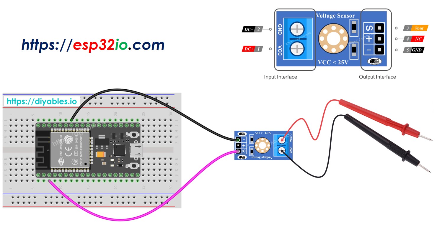
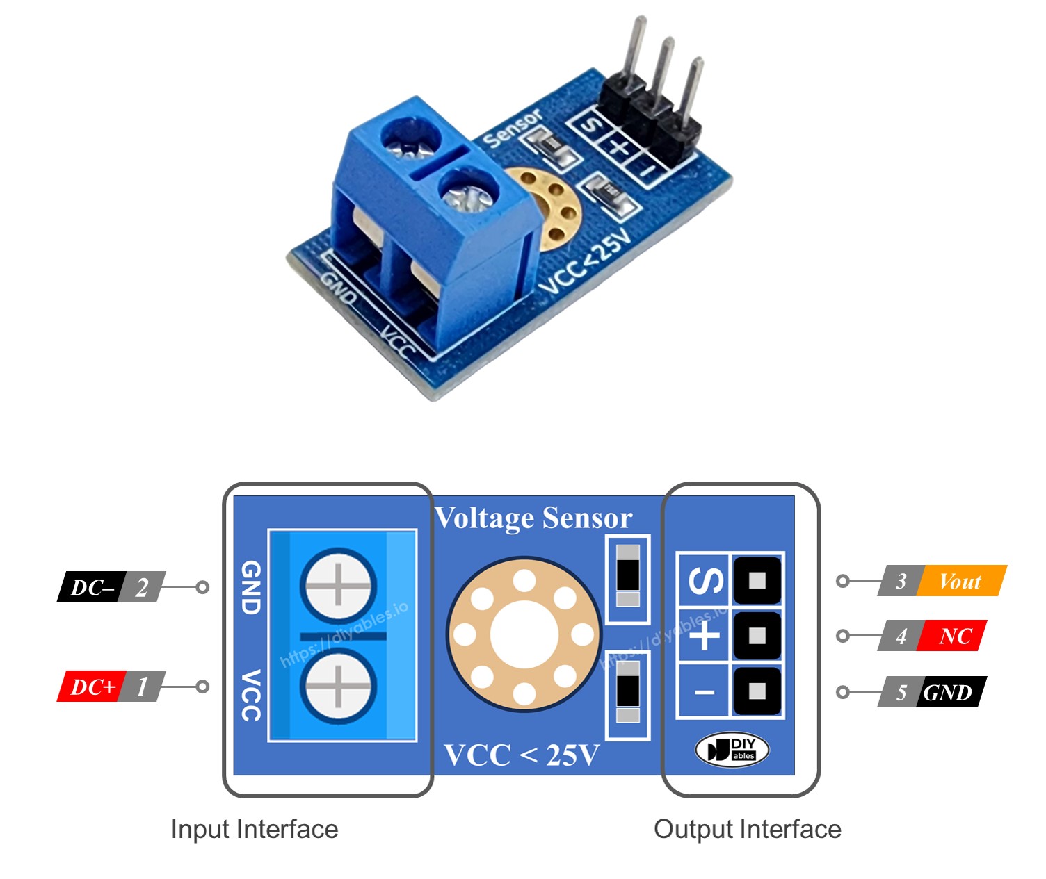
A Voltage Sensor is a ready-made voltage divider circuit that uses specific resistors to make measuring voltage easy. It has two resistors: one is 30 KΩ and the other is 7.5 KΩ. If the ADC has a reference voltage of 5V, the sensor can measure voltages from 0 to 25V DC. When the ADC's reference voltage is 3.3V, it can measure voltages from 0 to 16.5V DC.
Pinout
A voltage sensor comes with two types of pins:
- Input Interface (connect where you want to measure voltage):
- VCC pin: Connect this positive pin to the higher voltage point.
- GND pin: Connect this negative pin to the lower voltage point.
- Output Interface (connect to the ESP32):
- Vout pin (S): Connect this signal pin to an analog pin on the ESP32.
- NC pin (+): Do not connect this; it is not used.
- GND pin (-): Connect this ground pin to the GND (0V) on the ESP32.
Wiring Diagram
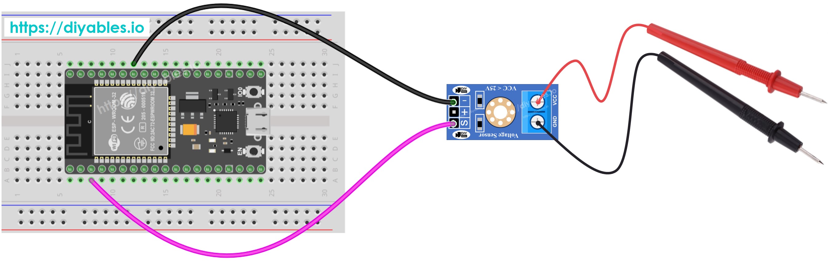
This image is created using Fritzing. Click to enlarge image
If you're unfamiliar with how to supply power to the ESP32 and other components, you can find guidance in the following tutorial: The best way to Power ESP32 and sensors/displays.
ESP32 Code
Quick Instructions
- If this is the first time you use ESP32, see how to setup environment for ESP32 on Arduino IDE.
- Connect the ESP32 to the voltage sensor.
- Connect the ESP32 board to your PC via a USB cable
- Open Arduino IDE on your PC.
- Select the right ESP32 board (e.g. ESP32 Dev Module) and COM port.
- Copy and paste the above code into the Arduino IDE.
- Press the Upload button in Arduino IDE to compile and upload the code to the ESP32.
- Test by measuring 5V and 3.3V on the ESP32.
- Check the readings on the Serial Monitor.
You might notice that the measurement result is incorrect or significantly different from the actual value. Do not blame the voltage sensor module for this. The code uses the analogRead() function to read values from an ADC (Analog-to-Digital Converter) connected to a voltage sensor. The ESP32 ADC is suitable for projects that do not require high accuracy. However, for projects needing precise measurements, please note:
- The ESP32 ADC is not perfectly accurate and might require calibration for correct results. Each ESP32 board can vary slightly, so calibration is needed for each individual board.
- Calibration can be challenging, especially for beginners, and might not always provide the exact results you want.
For projects requiring high precision, consider using an external ADC (e.g., ADS1115) with the ESP32 or an Arduino, which has a more reliable ADC. If you still want to calibrate the ESP32 ADC, refer to the ESP32 ADC Calibration Driver.
Video Tutorial
Making video is a time-consuming work. If the video tutorial is necessary for your learning, please let us know by subscribing to our YouTube channel , If the demand for video is high, we will make the video tutorial.