ESP32 - Car
One of the coolest things to try if you're just starting with ESP32 is making a robot car. In this guide, we'll learn how to use ESP32 to build a robot car and control it with a IR remote control. For controlling the robot car via Web (Wifi), see ESP32 controls Car via Web tutorial.
Hardware Used In This Tutorial
Or you can buy the following kits:
| 1 | × | DIYables ESP32 Starter Kit (ESP32 included) | |
| 1 | × | DIYables Sensor Kit (18 sensors/displays) |
Introduction to Robot Car
In the ESP32 context, the robot car is often called by different names like robot car, RC car, remote control car, smart car, or DIY car. It can be controlled from a distance without any wires. You can use either a special remote control that uses infrared light or a smartphone app through Bluetooth or WiFi. The robot car can go left or right and also go forward or backward.
A 2WD (Two-Wheel Drive) car for ESP32 is a small robotic vehicle that you can build and control using an ESP32 board. It typically consists of the following components:
- Chassis: The base or frame of the car,where all other components are mounted.
- Wheels: The two wheels that provide locomotion to the car. They are attached to two DC motor.
- Motors: Two DC motors are used to drive the two wheels.
- Motor Driver: The motor driver board is an essential component that interfaces between the ESP32 and the motors. It takes signals from the ESP32 and provides the necessary power and control to the motors.
- ESP32 Board: The brain of the car. It reads inputs from sensors and user commands and controls the motors accordingly.
- Power Source: The 2WD car requires a power source, usually batteries and a battery holder, to power the motors and the ESP32 board.
- Wireless receiver: an infrared, Bluetooth or WiFi module for wireless communication with a remote control or smartphone.
- Optional Components: Depending on your project's complexity, you may add various optional components like sensors (e.g., ultrasonic sensors for obstacle avoidance, line-following sensors), and more.
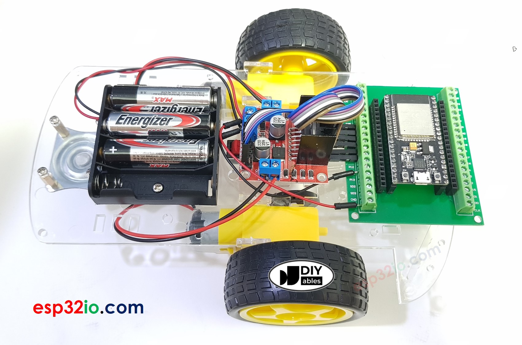
In this tutorial, to make it simple, we will use:
- 2WD Car kit (including Chassis, wheels, motors, battery holder)
- L298N Motor Driver
- IR infrared kit (including IR controller and IR receiver)
Check the hardware list at the top of this page.
How It Works
- ESP32 connects to the DC motors of the robot car through L298N motor driver module.
- ESP32 connects to an IR receiver.
- The battery powers ESP32, DC motors, motor driver, and IR receiver.
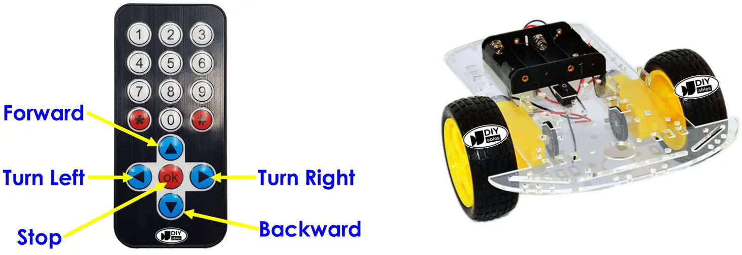
- Users press the UP/DOWN/LEFT/RIGHT/OK keys on the IR remote controller.
- ESP32 receives the UP/DOWN/LEFT/RIGHT/OK commands through the IR receiver.
- ESP32 controls the car to move FORWARD/BACKWARD/LEFT/RIGHT/STOP by controlling the DC motor via the motor driver.
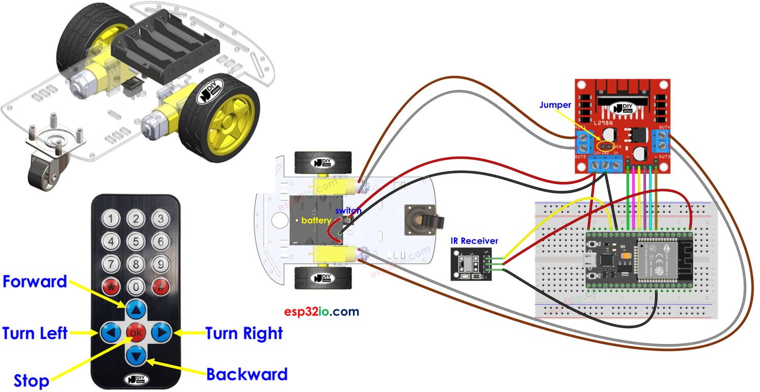
Wiring Diagram
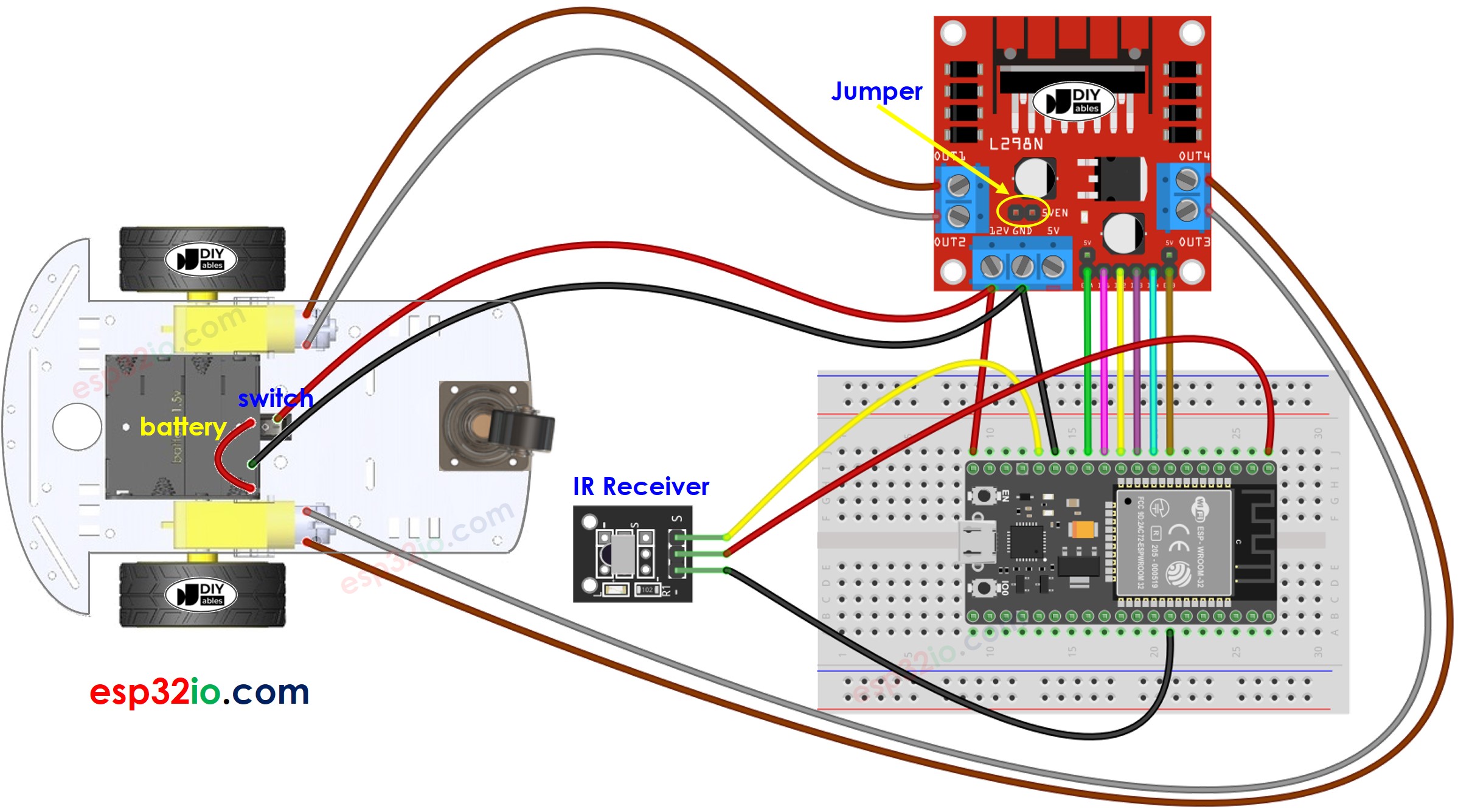
This image is created using Fritzing. Click to enlarge image
Usually, It requires two sources of power:
- One for the motor (indirectly through the L298N module).
- Another for the ESP32 board, the L298N module, and the IR receiver.
However, there's a method to simplify this by using only one power source for everything. You can achieve this by using four 1.5V batteries (totaling 6V). Here's how you can do it:
- Connect the batteries to the L298N module as shown in the diagram.
- Remove two jumpers that connect the ENA and ENB pins to 5 volts on the L298N module.
- Place a jumper labeled 5VEN, which is marked with a yellow circle on the diagram.
- Connect the 12V pin on the screw terminal of the L298N module to the Vin pin on the ESP32 board. This provides power to the ESP32 directly from batteries (6V).
If you're unfamiliar with how to supply power to the ESP32 and other components, you can find guidance in the following tutorial: The best way to Power ESP32 and sensors/displays.
ESP32 Code
Quick Instructions
- If this is the first time you use ESP32, see how to setup environment for ESP32 on Arduino IDE.
- Install DIYables_IRcontroller library on Arduino IDE by following this instruction
- Do the wiring as the diagram shown above.
- Disconnect the wire from the Vin on the ESP32 because we will power ESP32 via USB cable when uploading code.
- Flip the car upside down so that the wheels are on top.
- Connect the ESP32 board to your PC via a micro USB cable
- Open Arduino IDE on your PC.
- Select the right ESP32 board (e.g. ESP32 Dev Module) and COM port.
- Copy the provided code and open it in the Arduino IDE.
- Click the Upload button in the Arduino IDE to transfer the code to the ESP32.
- Use the IR remote controller to make the car go forward, backward, left, right, or stop.
- Check if the wheels move correctly according to your commands.
- If the wheels move the wrong way, swap the wires of the DC motor on the L298N module.
- You can also see the results on the Serial Monitor in the Arduino IDE.
- If everything is going well, unplug the USB cable from the ESP32, and then connect the wire back into the Vin 5V pin. This will give power to the ESP32 from the battery.
- Flip the car back to its normal position with the wheels on the ground.
- Have fun controlling the car!
Code Explanation
Read the line-by-line explanation in comment lines of code!
You can learn more about the code by checking the following tutorials:
- ESP32 - Infrared Remote Control tutorial
- ESP32 - DC motor tutorial
You can extend this project by:
- Adding obstacle avoidance sensors to immidilately stop the car if an obstacle is detected.
- Adding function to control the speed of car (see ESP32 - DC motor tutorial). The provided code controls car with full speed.
Video Tutorial
Making video is a time-consuming work. If the video tutorial is necessary for your learning, please let us know by subscribing to our YouTube channel , If the demand for video is high, we will make the video tutorial.