ESP32 - Traffic Light
In this tutorial, we will explore how to utilize the ESP32 to control a traffic light module. In detail, we will learn:
- How to connect the traffic light module to ESP32
- How to program ESP32 to control RGB traffic light module
- How to program ESP32 to control RGB traffic light module without using delay() function
This tutorial shows how to program the ESP32 using the Arduino language (C/C++) via the Arduino IDE. If you’d like to learn how to program the ESP32 with MicroPython, visit this ESP32 MicroPython - Traffic Light tutorial.
Hardware Used In This Tutorial
Or you can buy the following kits:
| 1 | × | DIYables ESP32 Starter Kit (ESP32 included) | |
| 1 | × | DIYables Sensor Kit (18 sensors/displays) |
Introduction to Traffic Light Module
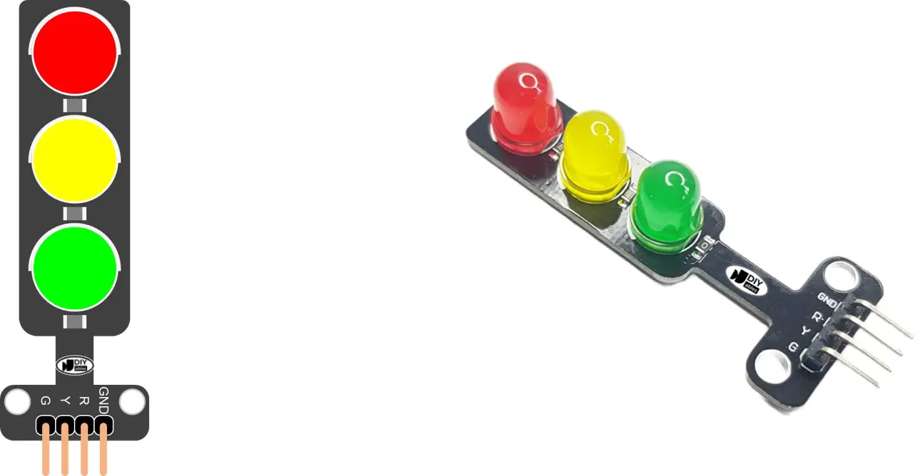
Pinout
A traffic light module includes 4 pins:
- GND pin: The ground pin, connect this pin to GND of ESP32.
- R pin: The pin to control the red light, connect this pin to a digital output of ESP32.
- Y pin: The pin to control the yellow light, connect this pin to a digital output of ESP32.
- G pin: The pin to control the green light, connect this pin to a digital output of ESP32.
How It Works
Wiring Diagram
- How to connect ESP32 and traffic light using breadboard
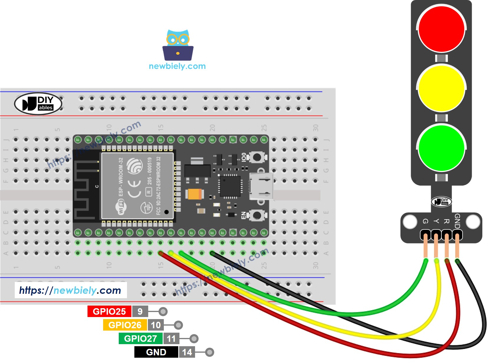
This image is created using Fritzing. Click to enlarge image
- How to connect ESP32 and traffic light using screw terminal block breakout board
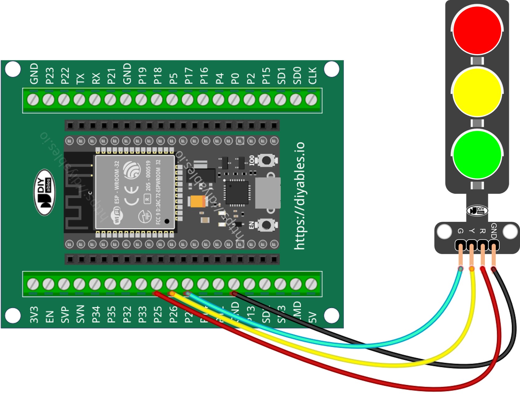
If you're unfamiliar with how to supply power to the ESP32 and other components, you can find guidance in the following tutorial: The best way to Power ESP32 and sensors/displays.
How To Program For Traffic Light module
- Configure an ESP32's pins to the digital output mode by using pinMode() function
- Program to turn ON red light by using digitalWrite() function:
ESP32 Code
Quick Instructions
- If this is the first time you use ESP32, see how to setup environment for ESP32 on Arduino IDE.
- Do the wiring as above image.
- Connect the ESP32 board to your PC via a micro USB cable
- Open Arduino IDE on your PC.
- Select the right ESP32 board (e.g. ESP32 Dev Module) and COM port.
- Copy the above code and open with Arduino IDE
- Click Upload button on Arduino IDE to upload code to ESP32
- Check out the traffic light module
It's important to note that the exact workings of a traffic light can vary depending on the specific design and technology used in different regions and intersections. The principles described above provide a general understanding of how traffic lights operate to manage traffic and enhance safety on the roads.
The code above demonstrates individual light control. Now, let's enhance the code for better optimization.
ESP32 Code Optimization
- Let's improve the code by implementing a function for light control.
- Let's improve the code by using a for loop.
- Let's improve the code by using millis() function intead of delay().
Video Tutorial
Making video is a time-consuming work. If the video tutorial is necessary for your learning, please let us know by subscribing to our YouTube channel , If the demand for video is high, we will make the video tutorial.