ESP32 - RGB LED
This tutorial instructs you how to control RGB LED to emit any color using ESP32.
This tutorial shows how to program the ESP32 using the Arduino language (C/C++) via the Arduino IDE. If you’d like to learn how to program the ESP32 with MicroPython, visit this ESP32 MicroPython - RGB LED tutorial.
Hardware Used In This Tutorial
Or you can buy the following kits:
| 1 | × | DIYables ESP32 Starter Kit (ESP32 included) | |
| 1 | × | DIYables Sensor Kit (18 sensors/displays) |
Introduction to RGB LED
The RGB LED can emit any colors by mixing the 3 basic colors red, green and blue. A single RGB LED is composed of 3 LEDs: red, green and blue. These three LEDs are packed into a single case so that it looks like a single LED.
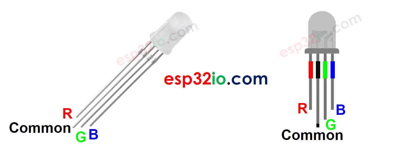
RGB LED Pinout
RGB LED includes four pins:
- R (red) pin: is to control the red color element
- G (green) pin: is to control the green color element
- B (blue) pin: is to control the blue color element
- Common (Cathode-) pin: connect this pin to GND (0V)
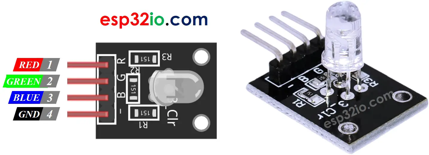
To hook up RGB LED to ESP32, we gotta add current-limiting resistors. This can complicate the wiring. Luckily, we can use an RGB LED module that comes with pre-built current-limiting resistors.
RGB LED Module also includes four pins:
- Common (Cathode-) pin: needs to be connected to GND (0V)
- R (red): pin is used to control red
- G (green): pin is used to control green
- B (blue): pin is used to control blue
※ NOTE THAT:
According to the common pin, there are two types of LED: common anode and common cathode. This tutorial uses a common cathode LED.
How RGB LED works
In term of physics, a color is a combination of three color elements: Red (R), Green (G) and Blue (B). Each color element's value range is from 0 to 255. The combination of values of three color elements create 256 x 256 x 256 colors in total.
If we generate PWM signals to R, G, B pins, the RGB LED diplays a color corresponding to the PWM duty cycle values. By changing the duty cycle of PWM signals (from 0 to 255), the RGB LED can display any color. The color values of Red (R), Grean (G) and Blue (B) correspond to PWM duty cycle on R, G and B pins , respectively.
Wiring Diagram between RGB LED and ESP32
- Wiring diagram between ESP32 and RGB LED
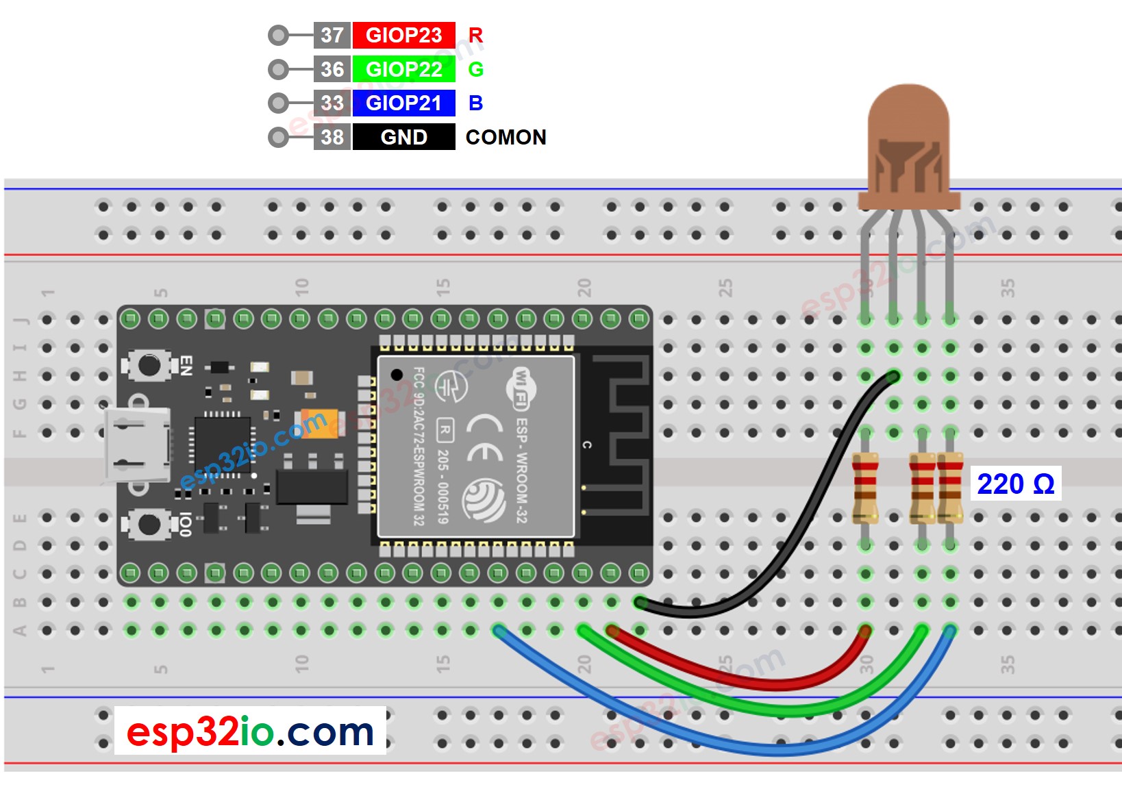
This image is created using Fritzing. Click to enlarge image
- Wiring diagram between ESP32 and RGB LED module
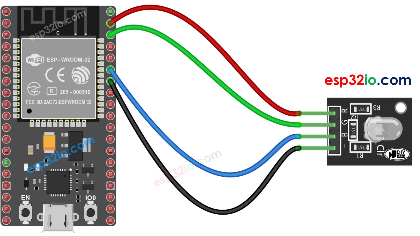
This image is created using Fritzing. Click to enlarge image
If you're unfamiliar with how to supply power to the ESP32 and other components, you can find guidance in the following tutorial: The best way to Power ESP32 and sensors/displays.
How To Control RGB LED
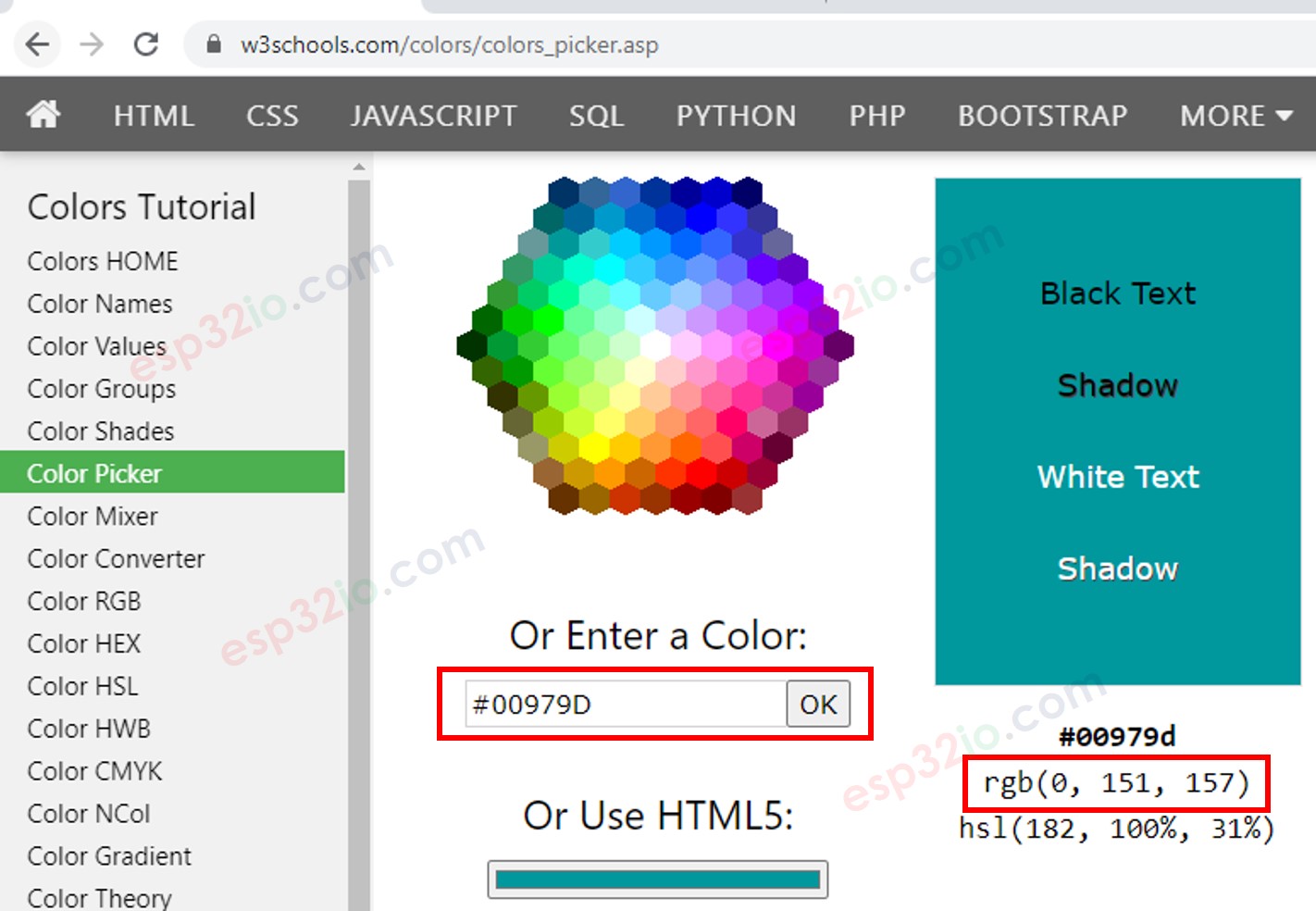
Let's assume that we want to display #00979D color on RGB LED, we can do the following step:
- Find the color code. Tips:
- You can pick up color code you want from the color picker
- If you want to use color in an image, use online Colors From Image tool
- Convert color code to R, G, B values using the tool from w3school. Take note these values. in this case: R = 0, G = 151, B = 157
- Define ESP32 pins that connects to R, G, and B pins. For example:
- Configure these ESP32 pins to the output mode
- Control LED to emit that color (#00979D → R = 0, G = 151, B = 157)
ESP32 - RGB LED Example Code
The below code changes color of LED among following colors in sequence:
- #00C9CC (R = 0, G = 201, B = 204)
- #F7788A (R = 247, G = 120, B = 138)
- #34A853 (R = 52, G = 168, B = 83)