ESP32 - Solenoid Lock
The Solenoid Lock is also known as the Electric Strike Lock. It can be use to lock/unlock cabinet, drawer, door. This tutorial instructs you how to use ESP32 to control the solenoid lock.
An alternative to the Solenoid Lock is Electromagnetic Lock. You can learn more in ESP32 - Electromagnetic Lock tutorial
This tutorial shows how to program the ESP32 using the Arduino language (C/C++) via the Arduino IDE. If you’d like to learn how to program the ESP32 with MicroPython, visit this ESP32 MicroPython - Solenoid Lock tutorial.
Hardware Used In This Tutorial
Or you can buy the following kits:
| 1 | × | DIYables ESP32 Starter Kit (ESP32 included) | |
| 1 | × | DIYables Sensor Kit (18 sensors/displays) |
Introduction to Solenoid Lock
Pinout
Solenoid Lock includes two wires:
- Positive (+) wire (red): needs to be connected to 12V of DC power supply
- Negative (-) wire (black): needs to be connected to GND of DC power supply
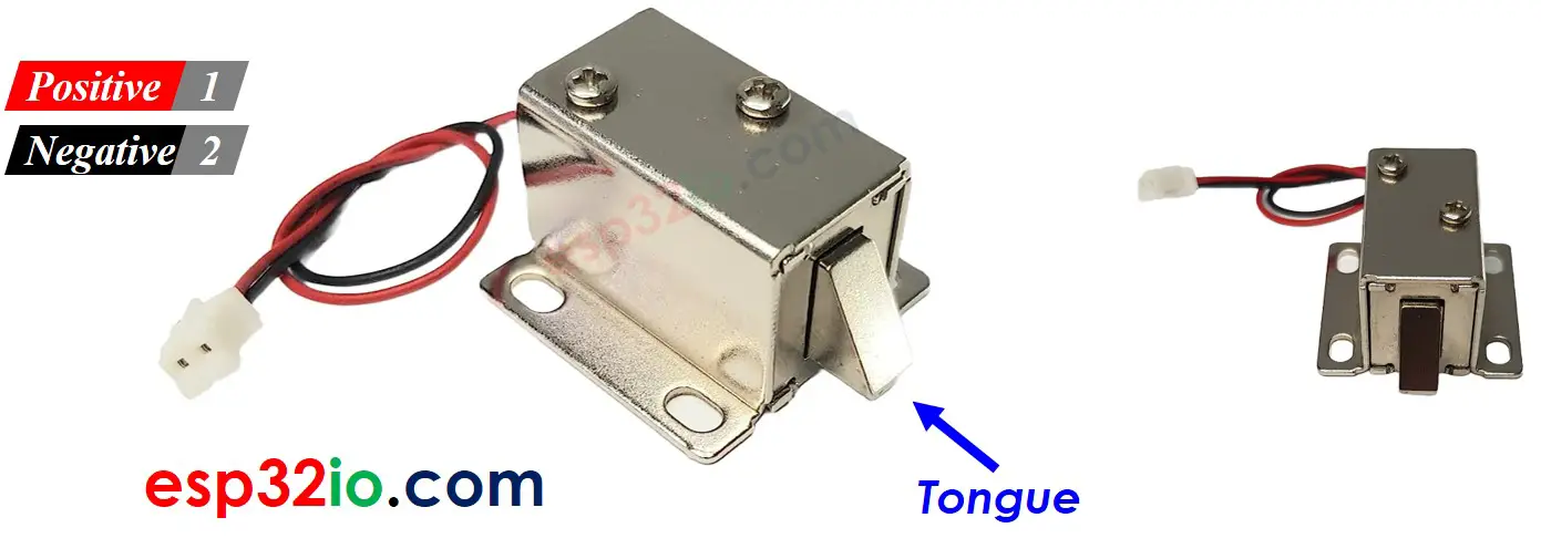
How It Works
- When the Solenoid Lock is powered, the lock tongue (strike) is extended ⇒ the door is locked
- When the Solenoid Lock is NOT powered, the lock tongue (strike) is retracted ⇒ the door is unlocked
※ NOTE THAT:
The solenoid lock usually uses 12V, 24V or 48V power supply. Therefore, we CANNOT connect the solenoid lock directly to ESP32 pin. We have to connect it to ESP32 pin via a relay
If we connect the solenoid lock to a relay (normally open mode):
- When relay is open, door is unlocked
- When relay is closed, door is locked
By connecting ESP32 to the relay, we can program for ESP32 to control the solenoid lock. Learn more about relay in ESP32 - Relay tutorial.
Wiring Diagram
- How to connect ESP32 and solenoid lock using breadboard (powered via USB cable)
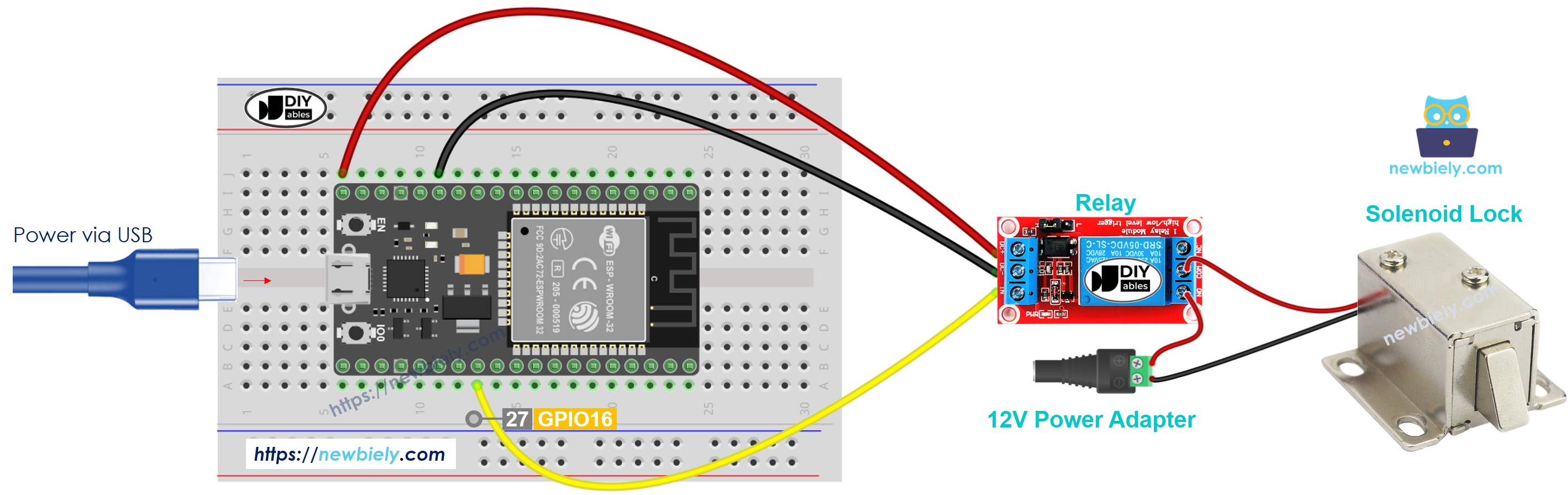
This image is created using Fritzing. Click to enlarge image
- How to connect ESP32 and solenoid lock using breadboard (powered via Vin pin)
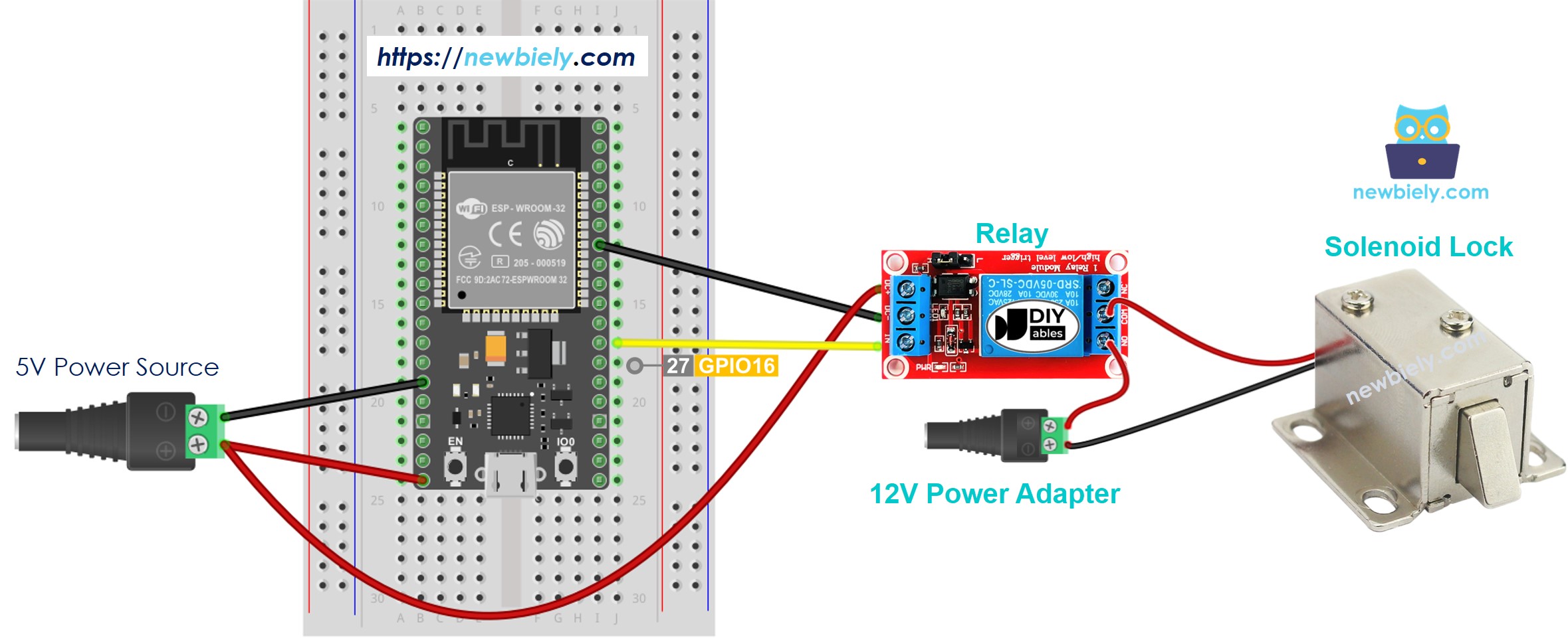
This image is created using Fritzing. Click to enlarge image
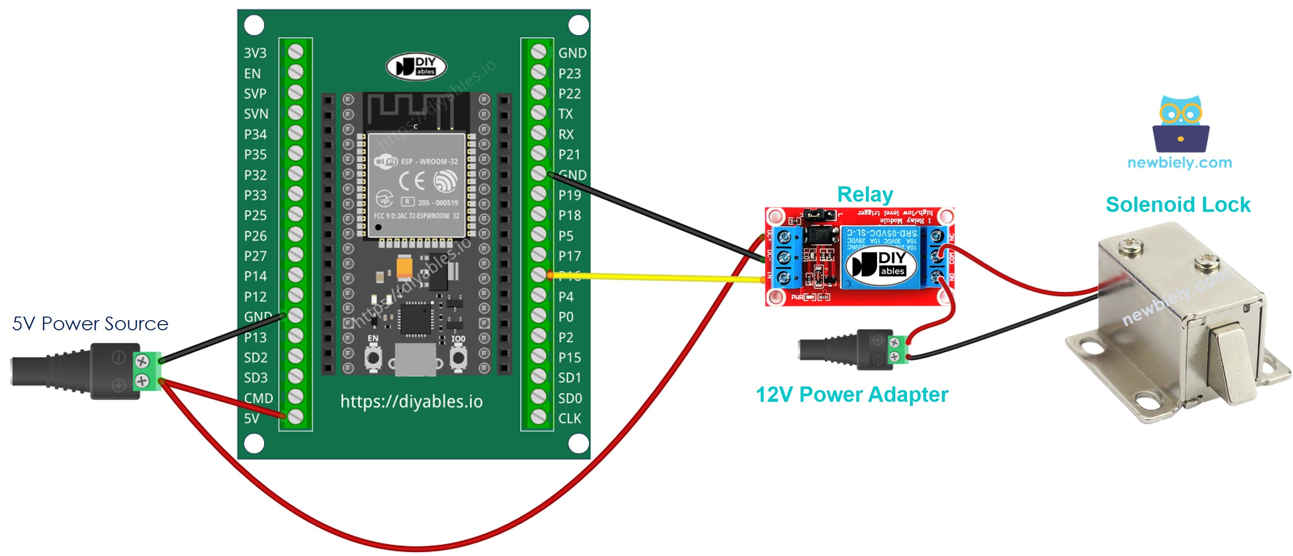
- How to connect ESP32 and solenoid lock using screw terminal block breakout board (powered via USB cable)
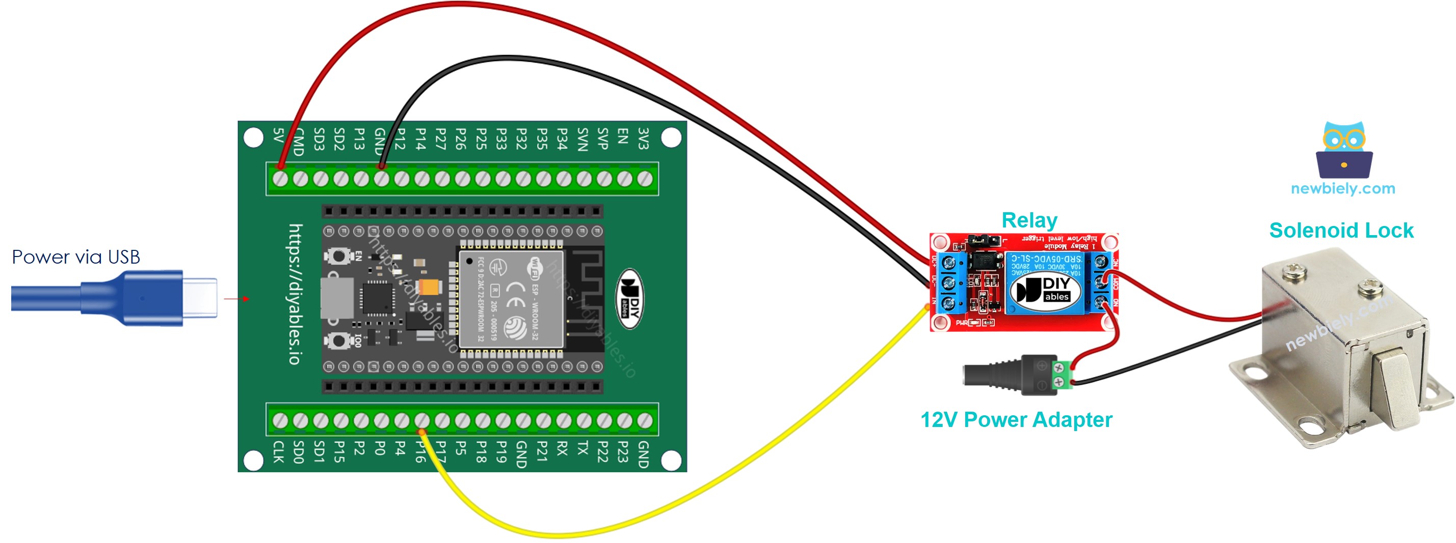
- How to connect ESP32 and solenoid lock using screw terminal block breakout board (powered via Vin pin)
If you're unfamiliar with how to supply power to the ESP32 and other components, you can find guidance in the following tutorial: The best way to Power ESP32 and sensors/displays.
ESP32 Code
The below code lock/unlock the door every 5 seconds
Quick Instructions
- If this is the first time you use ESP32, see how to setup environment for ESP32 on Arduino IDE.
- Do the wiring as above image.
- Connect the ESP32 board to your PC via a micro USB cable
- Open Arduino IDE on your PC.
- Select the right ESP32 board (e.g. ESP32 Dev Module) and COM port.
- Copy the above code and paste it to Arduino IDE
- Compile and upload code to ESP32 board by clicking Upload button on Arduino IDE
- See the the lock tongue's state
Video Tutorial
Making video is a time-consuming work. If the video tutorial is necessary for your learning, please let us know by subscribing to our YouTube channel , If the demand for video is high, we will make the video tutorial.