ESP32 RS485
This tutorial instructs you how to use RS485 communication with ESP32. In detail, we'll learn the following aspects:
- Establishing the connection between ESP32 and the TTL to RS485 module.
- Programming ESP32 to retrieve data from the TTL to RS485 module.
- Programming ESP32 to transmit data to the TTL to RS485 module.
- How to send data from your PC to ESP32 via RS485, and vice versa.
Hardware Used In This Tutorial
Or you can buy the following kits:
| 1 | × | DIYables ESP32 Starter Kit (ESP32 included) | |
| 1 | × | DIYables Sensor Kit (18 sensors/displays) |
Introduction to TTL to RS485 Module
When utilizing serial communication on the ESP32 with functions such as Serial.print(), Serial.read(), and Serial.write(), data transmission occurs via the TX pin, while data reception happens through the RX pin. These pins operate at TTL level, meaning they handle signals with a limited range. Hence, for serial communication over extended distances, converting the TTL signal to RS232, RS485, or RS422 signal standards becomes necessary.
In this tutorial, we'll explore the utilization of RS485 (also referred to as RS-485) with the ESP32 by employing a TTL to RS485 module. This module facilitates the conversion of TTL signals to RS485 signals and vice versa.
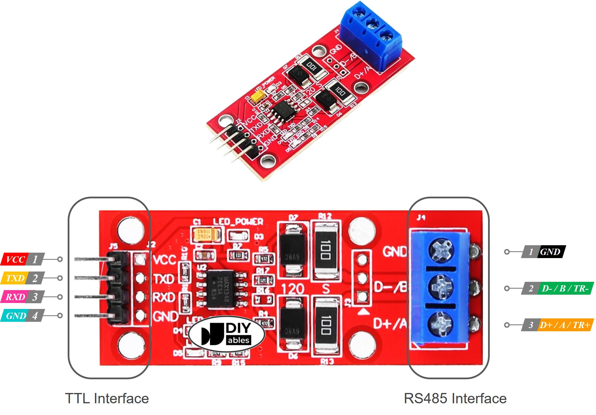
Pinout
The RS485 to TTL module features two interfaces:
- TTL Interface (connected to ESP32):
- VCC Pin: This power pin should be connected to VCC (5V or 3.3V).
- GND Pin: This power pin should be connected to GND (0V).
- RXD Pin: This data pin should be connected to a TX pin of the ESP32.
- TXD Pin: This data pin should be connected to an RX pin of the ESP32.
- RS485 Interface:
- D+ (A or TR+) Pin: This pin facilitates data communication.
- D- (B or TR-) Pin: This pin is utilized for data transmission.
- GND Pin: While optional, including this pin is strongly recommended to mitigate noise interference, ensuring optimal performance.
Wiring Diagram
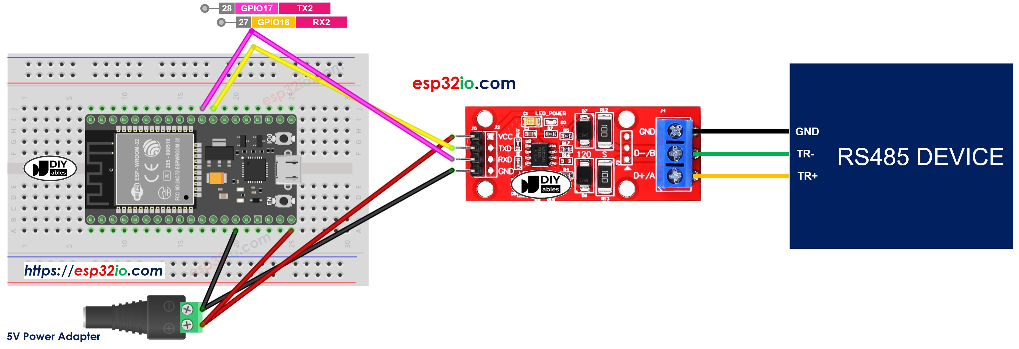
This image is created using Fritzing. Click to enlarge image
If you're unfamiliar with how to supply power to the ESP32 and other components, you can find guidance in the following tutorial: The best way to Power ESP32 and sensors/displays.
How To Program ESP32 to use the RS485 module
- Initializes the Serial interface:
- To read data come from RS485, you can use the following functions:
- To write data to RS485, you can use the following functions:
- And more functions to use with RS485 in Serial reference
ESP32 Code
Testing
You can do a test by sending data from your PC to ESP32 via RS-485 and vice versa. To do it, follow the below steps:
- Connect ESP32 to your PC via RS485-to-USB cable as below:
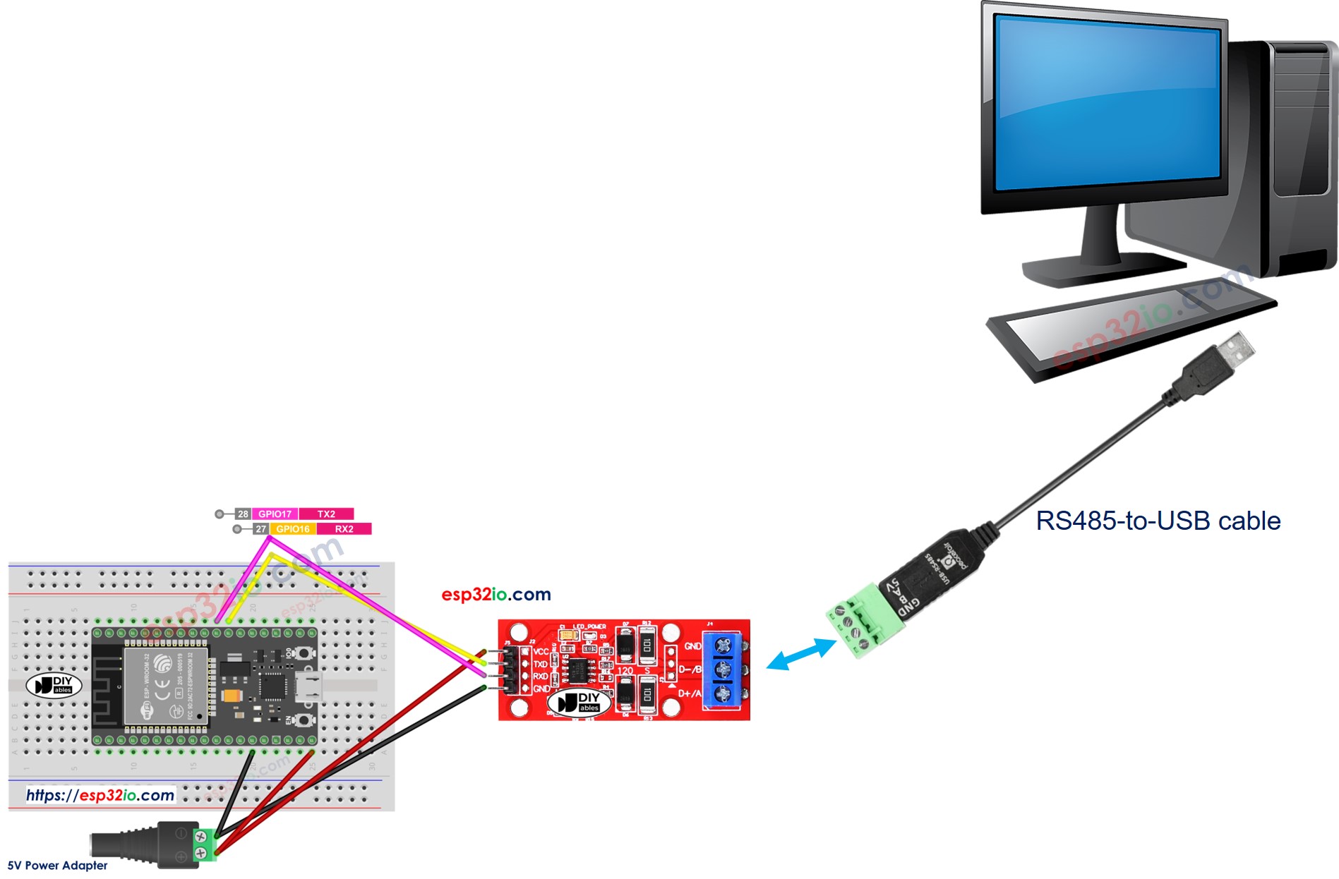
- Open the Serial Terminal Program and configure the Serial parameters (COM port, baurate...)
- Type some data from the Serial Termial to send it to ESP32.
- If successful, you will see the echo data on the Serial Terminal.
Video Tutorial
Making video is a time-consuming work. If the video tutorial is necessary for your learning, please let us know by subscribing to our YouTube channel , If the demand for video is high, we will make the video tutorial.