ESP32 - RFID/NFC Door Lock System

This tutorial instructs you how to use ESP32 to make an RFID/NFC door lock system.

※ NOTE THAT:

You can combine this door lock with the door lock system using keypad.

Hardware Used In This Tutorial

1×ESP-WROOM-32 Dev Module
1×USB Cable Type-C
1×RFID/NFC RC522 Kit (reader + tags)
1×RFID Key Fob
1×RFID Card
1×Solenoid Lock
1×(Aternative) Electromagnetic Lock
1×Relay
1×12V Power Adapter
10×Jumper Wires
1×(Optional) DC Power Jack
1×(Recommended) Screw Terminal Expansion Board for ESP32
1×(Recommended) Power Splitter For ESP32

Or you can buy the following sensor kits:

1×DIYables Sensor Kit (30 sensors/displays)
1×DIYables Sensor Kit (18 sensors/displays)
Disclosure: Some of the links in this section are Amazon affiliate links, meaning we may earn a commission at no additional cost to you if you make a purchase through them. Additionally, some links direct you to products from our own brand, DIYables .

Introduction to RFID/NFC RC522 Module and Electromagnetic Lock

We have specific tutorials about RFID/NFC RC522 module and Electromagnetic Lock. Each tutorial contains detailed information and step-by-step instructions about hardware pinout, working principle, wiring connection to ESP32, ESP32 code... Learn more about them at the following links:

System Components

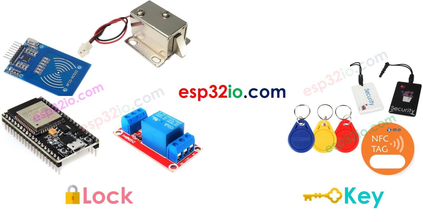
A door lock system includes two main parts:

  • Door Lock: ESP32, RFID/NFC reader, solenoid lock or electromagnetic lock
  • Door Key: RFID/NFC tags
ESP32 ESP32 rfid door lock component

How RFID/NFC Door Lock Works

  • The UIDs of authorized tags (key) are predefined in ESP32 code
  • When an RFID/NFC tag is tapped on RFID/NFC reader
  • ESP32 reads the UID from the reader
  • ESP32 compares the UID with the predefined UIDs
  • If one UID is matched, ESP32 deactivates the electromagnetic lock to unlock the door.

Wiring Diagram
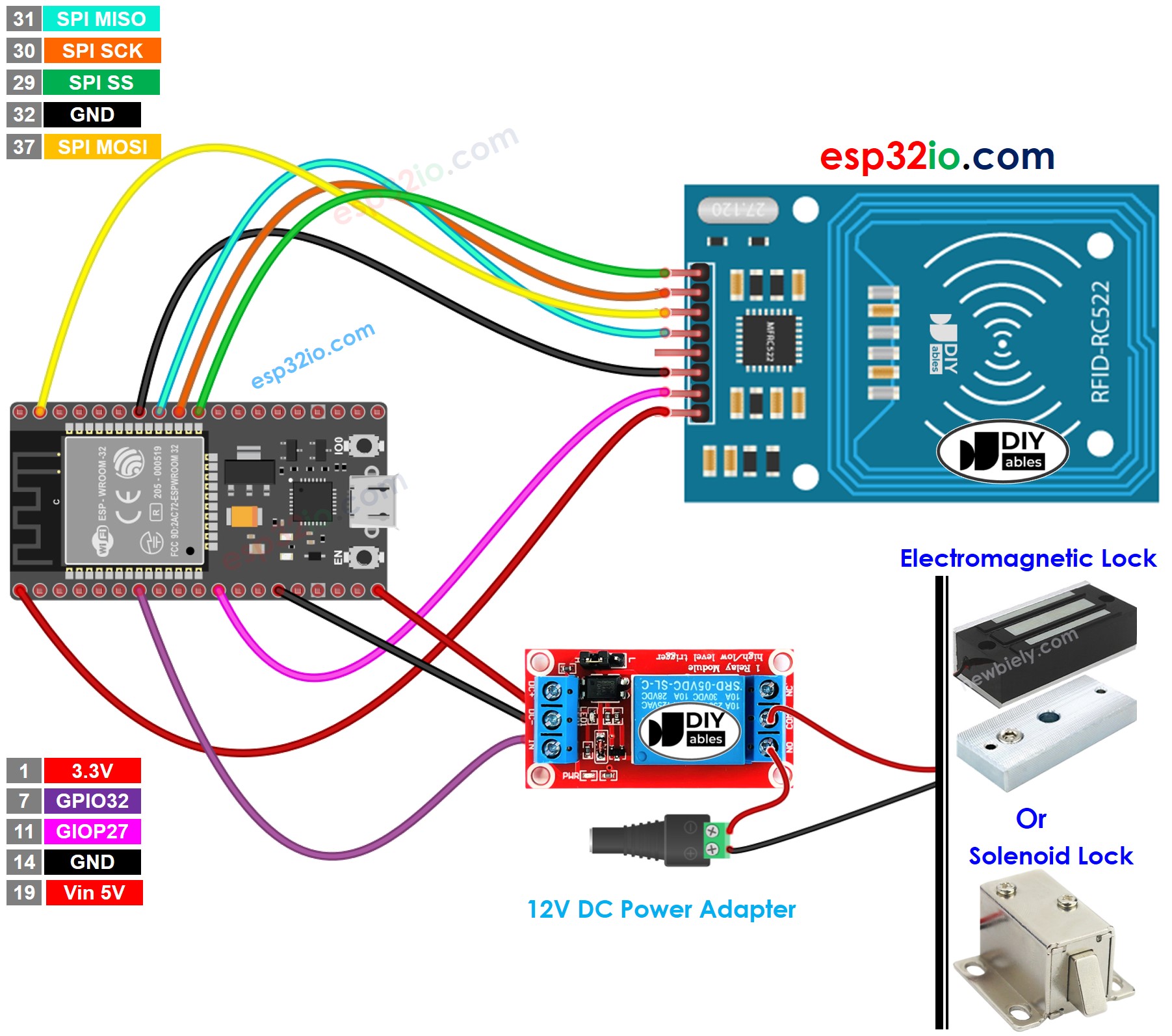
ESP32 RFID RC522 Door Lock System wiring diagram

This image is created using Fritzing. Click to enlarge image

※ NOTE THAT:

The pins order can vary according to manufacturers. ALWAYS use the labels printed on the module. The above image shows the pinout of the modules from DIYables manufacturer.

If you're unfamiliar with how to supply power to the ESP32 and other components, you can find guidance in the following tutorial: The best way to Power ESP32 and sensors/displays.

ESP32 Code - Single Key

/* * This ESP32 code is created by esp32io.com * * This ESP32 code is released in the public domain * * For more detail (instruction and wiring diagram), visit https://esp32io.com/tutorials/esp32-rfid-nfc-door-lock-system */ #include <SPI.h> #include <MFRC522.h> #define SS_PIN 5 // ESP32 pin GPIO5 #define RST_PIN 27 // ESP32 pin GPIO27 #define RELAY_PIN 32 // ESP32 pin GPIO32 connects to relay MFRC522 rfid(SS_PIN, RST_PIN); byte keyTagUID[4] = {0xFF, 0xFF, 0xFF, 0xFF}; void setup() { Serial.begin(9600); SPI.begin(); // init SPI bus rfid.PCD_Init(); // init MFRC522 pinMode(RELAY_PIN, OUTPUT); // initialize pin as an output. digitalWrite(RELAY_PIN, HIGH); // lock the door Serial.println("Tap an RFID/NFC tag on the RFID-RC522 reader"); } void loop() { if (rfid.PICC_IsNewCardPresent()) { // new tag is available if (rfid.PICC_ReadCardSerial()) { // NUID has been readed MFRC522::PICC_Type piccType = rfid.PICC_GetType(rfid.uid.sak); if (rfid.uid.uidByte[0] == keyTagUID[0] && rfid.uid.uidByte[1] == keyTagUID[1] && rfid.uid.uidByte[2] == keyTagUID[2] && rfid.uid.uidByte[3] == keyTagUID[3] ) { Serial.println("Access is granted"); digitalWrite(RELAY_PIN, LOW); // unlock the door for 2 seconds delay(2000); digitalWrite(RELAY_PIN, HIGH); // lock the door } else { Serial.print("Access denied, UID:"); for (int i = 0; i < rfid.uid.size; i++) { Serial.print(rfid.uid.uidByte[i] < 0x10 ? " 0" : " "); Serial.print(rfid.uid.uidByte[i], HEX); } Serial.println(); } rfid.PICC_HaltA(); // halt PICC rfid.PCD_StopCrypto1(); // stop encryption on PCD } } }

Quick Instructions

  • If this is the first time you use ESP32, see how to setup environment for ESP32 on Arduino IDE.
  • Click to the Libraries icon on the left bar of the Arduino IDE.
  • Type “MFRC522” on the search box, then look for the library by GithubCommunity
  • Install the library by clicking on Install button.
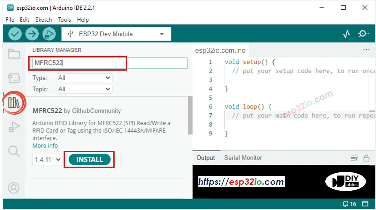
ESP32 MFRC522 library
  • Find out the tag's UID by doing the following steps:
    • Copy the above code and paste it to Arduino IDE.
    • Compile and upload code to ESP32 board by clicking Upload button on Arduino IDE
    • Open Serial Monitor on Arduino IDE
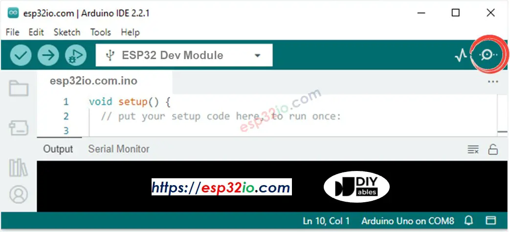
    How to open serial monitor on Arduino IDE
    • Tap an RFID/NFC tag that you want to give authorization on RFID-RC522 reader
    • Write down the UID printed on Serial Monitor
    COM6
    Send
    Tap an RFID/NFC tag on the RFID-RC522 reader Access denied, UID: 2B B8 59 B1
    Autoscroll Show timestamp
    Clear output
    9600 baud  
    Newline  
    • Update UID in the line 18 of the above code. For example, change byte keytagUID[4] = {0xFF, 0xFF, 0xFF, 0xFF}; TO byte keytagUID[4] = {0x2B, 0xB8, 0x59, 0xB1};
    • Upload the code to ESP32 again
    • Tap an RFID/NFC tag on RFID-RC522 module
    • See the result on Serial Monitor
    COM6
    Send
    Tap an RFID/NFC tag on the RFID-RC522 reader Access is granted
    Autoscroll Show timestamp
    Clear output
    9600 baud  
    Newline  
    • Check the electromagnetic lock, it should be deactivated
    • Tap another RFID/NFC tag on RFID-RC522 module
    • See the result on Serial Monitor
    COM6
    Send
    Tap an RFID/NFC tag on the RFID-RC522 reader Access is granted Access denied, UID: 1C 2A 52 E3
    Autoscroll Show timestamp
    Clear output
    9600 baud  
    Newline  

ESP32 Code - Multiple Keys

Let's make a lock that accepts two key: the manager key and secretary key to unlock the door.

/* * This ESP32 code is created by esp32io.com * * This ESP32 code is released in the public domain * * For more detail (instruction and wiring diagram), visit https://esp32io.com/tutorials/esp32-rfid-nfc-door-lock-system */ #include <SPI.h> #include <MFRC522.h> #define SS_PIN 5 // ESP32 pin GPIO5 #define RST_PIN 27 // ESP32 pin GPIO27 #define RELAY_PIN 32 // ESP32 pin GPIO32 connects to relay MFRC522 rfid(SS_PIN, RST_PIN); byte managerKeyUID[4] = {0x3A, 0xC9, 0x6A, 0xCB}; byte secretaryKeyUID[4] = {0x30, 0x01, 0x8B, 0x15}; void setup() { Serial.begin(9600); SPI.begin(); // init SPI bus rfid.PCD_Init(); // init MFRC522 pinMode(RELAY_PIN, OUTPUT); // initialize pin as an output. digitalWrite(RELAY_PIN, HIGH); // lock the door Serial.println("Tap an RFID/NFC tag on the RFID-RC522 reader"); } void loop() { if (rfid.PICC_IsNewCardPresent()) { // new tag is available if (rfid.PICC_ReadCardSerial()) { // NUID has been readed MFRC522::PICC_Type piccType = rfid.PICC_GetType(rfid.uid.sak); if (rfid.uid.uidByte[0] == managerKeyUID[0] && rfid.uid.uidByte[1] == managerKeyUID[1] && rfid.uid.uidByte[2] == managerKeyUID[2] && rfid.uid.uidByte[3] == managerKeyUID[3] ) { Serial.println("The access is granted to manager"); digitalWrite(RELAY_PIN, LOW); // unlock the door for 2 seconds delay(2000); digitalWrite(RELAY_PIN, HIGH); // lock the door } else if (rfid.uid.uidByte[0] == secretaryKeyUID[0] && rfid.uid.uidByte[1] == secretaryKeyUID[1] && rfid.uid.uidByte[2] == secretaryKeyUID[2] && rfid.uid.uidByte[3] == secretaryKeyUID[3] ) { Serial.println("The access is granted to secretary"); digitalWrite(RELAY_PIN, LOW); // unlock the door for 2 seconds delay(2000); digitalWrite(RELAY_PIN, HIGH); // lock the door } else { Serial.print("Access denied, UID:"); for (int i = 0; i < rfid.uid.size; i++) { Serial.print(rfid.uid.uidByte[i] < 0x10 ? " 0" : " "); Serial.print(rfid.uid.uidByte[i], HEX); } Serial.println(); } rfid.PICC_HaltA(); // halt PICC rfid.PCD_StopCrypto1(); // stop encryption on PCD } } }

Quick Instructions

  • Updated two authorized RFID/NFC tag's UUID to the code
  • Upload the code to ESP32
  • Tap the authorized tags one-by-one on RFID-RC522 module.
  • The result on Serial Monitor:
COM6
Send
Tap an RFID/NFC tag on the RFID-RC522 reader The access is granted to manager The access is granted to secretary
Autoscroll Show timestamp
Clear output
9600 baud  
Newline  

You can modify the code to add three, four, or more tags.

Video Tutorial

Making video is a time-consuming work. If the video tutorial is necessary for your learning, please let us know by subscribing to our YouTube channel , If the demand for video is high, we will make the video tutorial.

※ OUR MESSAGES