ESP32 - Joystick
In this tutorial, we are going to learn how to use Joystick with ESP32. In detail, we will learn:
- How Joystick works
- How to connect Joystick to ESP32 and program for it
- How to convert the values from Joystick to controllable values such as XY coordinates, the motor's up/down/left/right direction...
This tutorial shows how to program the ESP32 using the Arduino language (C/C++) via the Arduino IDE. If you’d like to learn how to program the ESP32 with MicroPython, visit this ESP32 MicroPython - Joystick tutorial.
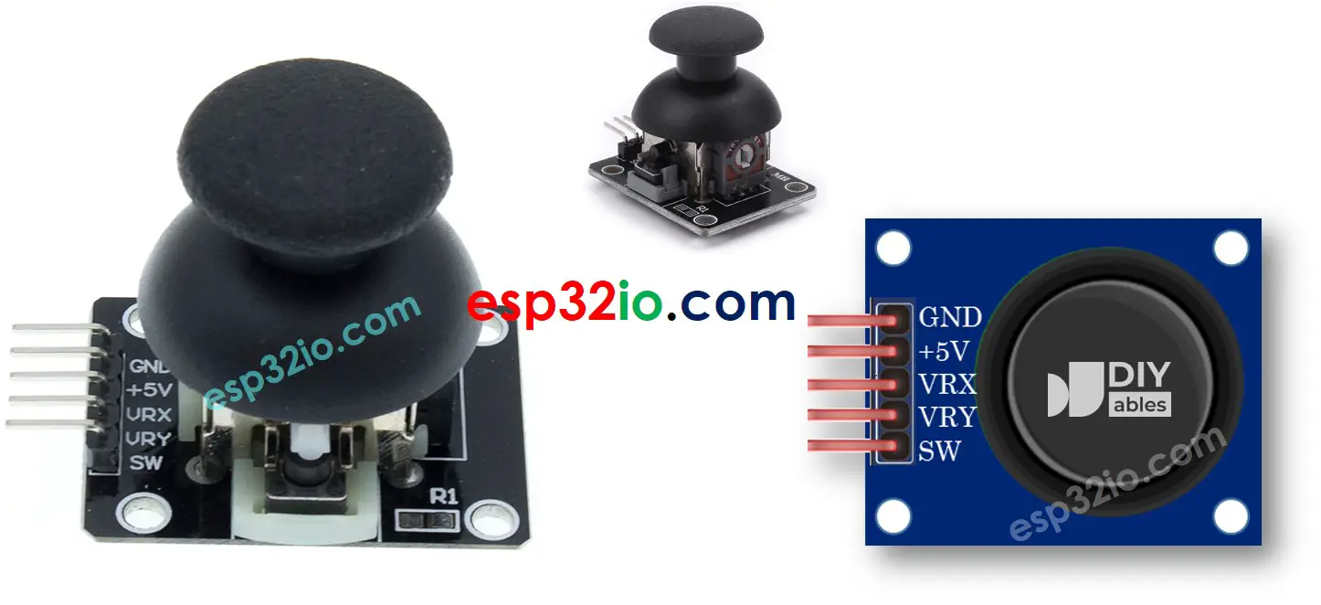
Hardware Used In This Tutorial
Or you can buy the following kits:
| 1 | × | DIYables ESP32 Starter Kit (ESP32 included) | |
| 1 | × | DIYables Sensor Kit (18 sensors/displays) |
Introduction to Joystick Sensor
You probably see the Joystick somewhere such as a game controller, toy controller, or even a big real machine such as an excavator controller.
The joystick is composed of two potentiometers square with each other, and one push button. Therefore, it provides the following outputs:
- An analog value (from 0 to 4095) corresponding to the horizontal position (called X-coordinate)
- An analog value (from 0 to 4095) corresponding to the vertical position (called Y-coordinate)
- A digital value of a pushbutton (HIGH or LOW)
The combination of two analog values can create 2-D coordinates with the center are values when the joystick is in the rest position. The real direction of the coordinates can be identified simply when you run a test code (in the next part).
Some applications may use all three outputs, some applications may use some of three outputs.
Pinout
A Joystick has 5 pins:
- GND pin: needs to be connected to GND (0V)
- VCC pin: needs to be connected to VCC (5V)
- VRX pin: outputs an analog value corresponding to the horizontal position (called X-coordinate).
- VRY pin: outputs an analog value corresponding to the vertical position (called Y-coordinate).
- SW pin: is the output from the pushbutton inside the joystick. It’s normally open. If we use a pull-up resistor in this pin, the SW pin will be HIGH when it is not pressed, and LOW when it is pressed.
How It Works
- When you push the joystick's thump to left/right, the voltage in the VRX pin is changed, The voltage range is from 0 to 5V (0 at left and 5v at right). The voltage value is in proportion to the position of the thump ⇒ The reading value on ESP32's analog pin is from 0 to 4095
- When you push the joystick's thump to up/down, the voltage in the VRY pin is changed, The voltage range is from 0 to 5V (0 at up and 5v at down). The voltage value is in proportion to the position of the thump ⇒ The reading value on ESP32's analog pin is from 0 to 4095
- When you push the joystick's thump to any direction, the voltage in both VRX and VRY pins is changed in proportion to the projection of position on each axis
- When you push the joystick's thump from top to bottom, the pushbutton inside the joystick is closed, If we use a pull-up resistor in the SW pin, the output from SW pin will change from 5V to 0V ⇒ The reading value on ESP32's digital pin is changed from HIGH to LOW
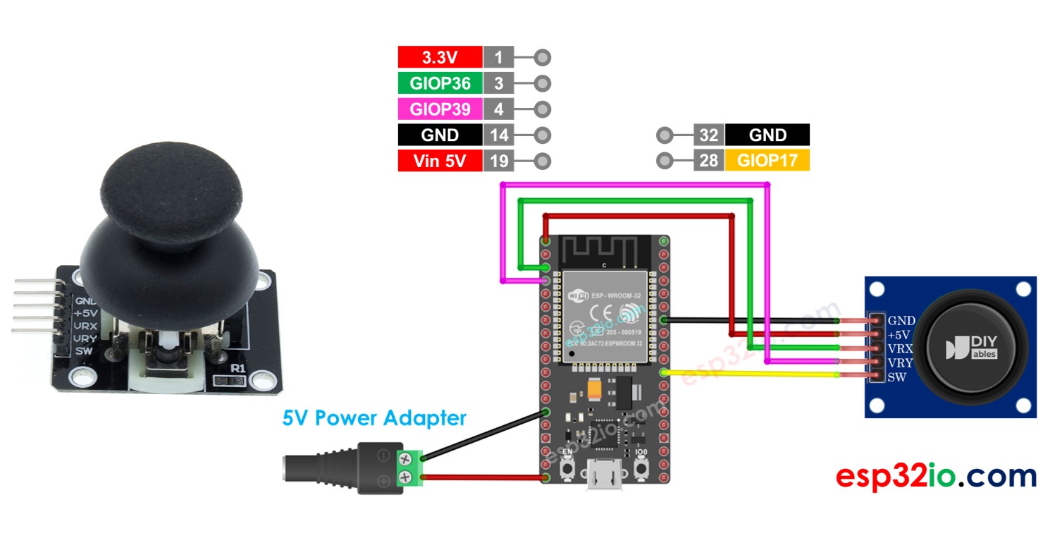
Wiring Diagram
- How to connect ESP32 and joystick using breadboard
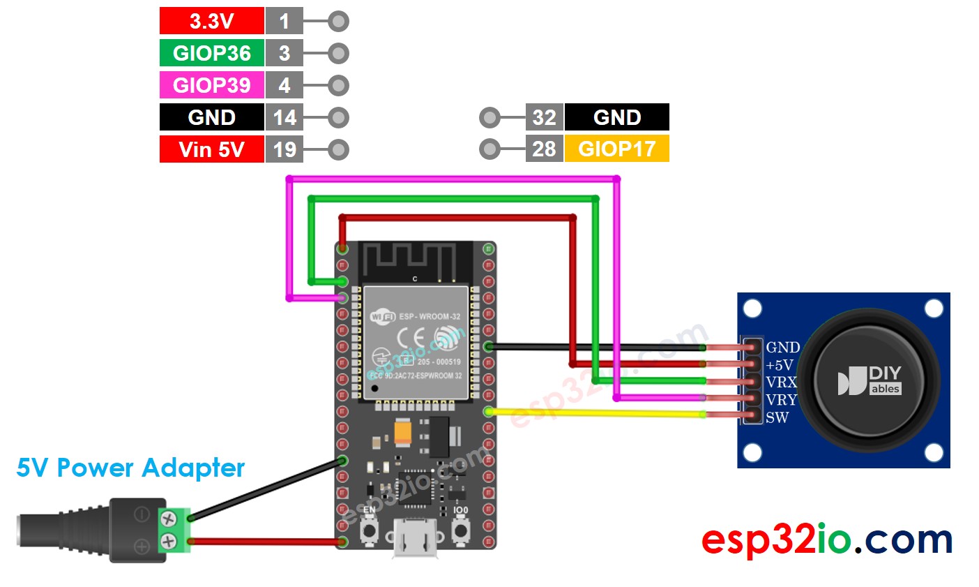
This image is created using Fritzing. Click to enlarge image
- How to connect ESP32 and joystick using screw terminal block breakout board
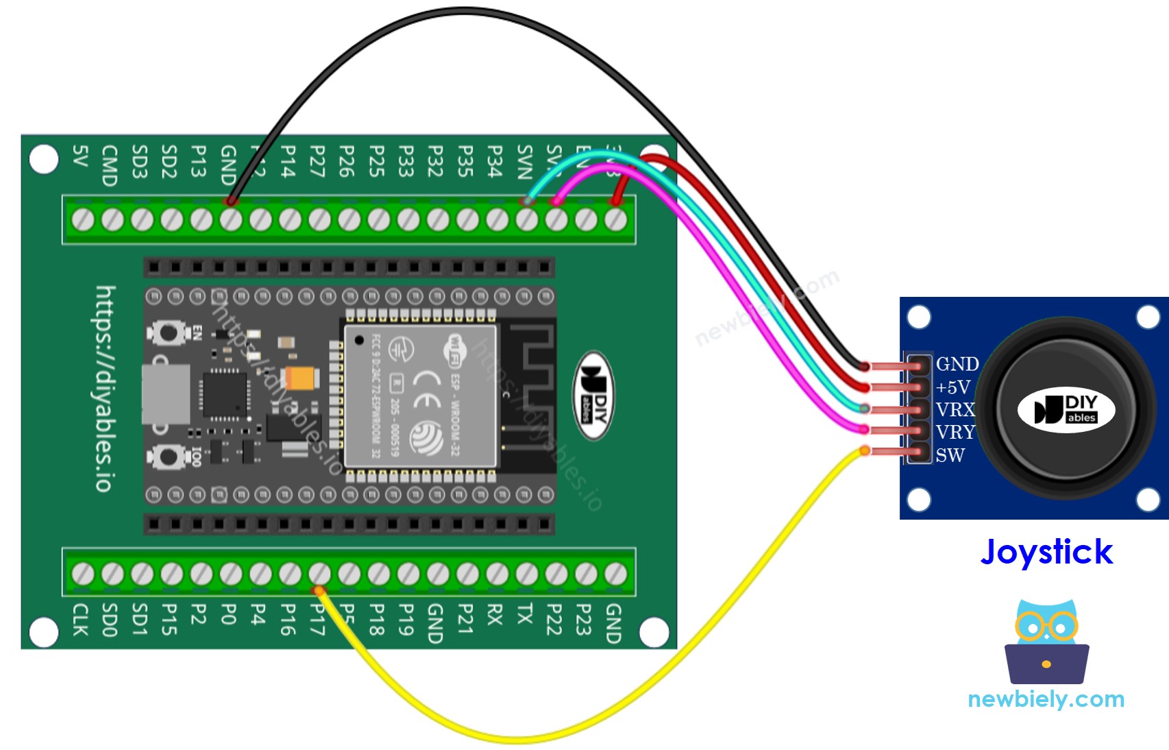
If you're unfamiliar with how to supply power to the ESP32 and other components, you can find guidance in the following tutorial: The best way to Power ESP32 and sensors/displays.
How To Program For Joystick
The joystick has two parts: analog (X, Y axis) and digital (pushbutton)
- For the analog parts (X, Y axis), it just need to read the value from analog input pin by using analogRead() function.
- For the digital part (pushbutton): it is a button. The most simple and convenient way is to use ezButton library. This library supports debounce for buttons and also enables an internal pull-up resistor. You can see more about button in ESP32 - Button tutorial. The code will be presented in the next session in this tutorial.
After reading the values from analog pins, we may need to convert them to some controllable values. The next part will provide the example codes for this.
ESP32 Code
This section will provide the following ESP32 example codes:
- Example code: reads analog values from joystick
- Example code: reads analog values and reads the button state from joystick
- Example code: converts analog value to MOVE_LEFT, MOVE_RIGHT, MOVE_UP, MOVE_DOWN commands
- Example code: converts analog values to angles to control two servo motors (e.g. in pan-tilt camere)
Reads analog values from joystick
Quick Instructions
- If this is the first time you use ESP32, see how to setup environment for ESP32 on Arduino IDE.
- Do the wiring as above image.
- Connect the ESP32 board to your PC via a micro USB cable
- Open Arduino IDE on your PC.
- Select the right ESP32 board (e.g. ESP32 Dev Module) and COM port.
- Copy the above code and open with Arduino IDE
- Click Upload button on Arduino IDE to upload code to ESP32
- Push the joystick's thump maximally to the limit, and then rotate it in a circle (clockwise or anti-clockwise)
- See the result on Serial Monitor.
- While rotating the joystick' thump, keep watching the Serial Monitor
- If the X value is 0, mark or memorize the current position as left ⇒ the opposite direction the right
- If the Y value is 0, mark or memorize the current position as up ⇒ the opposite direction the down
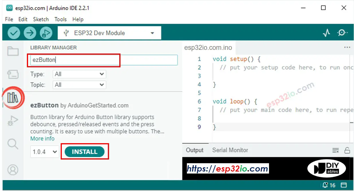
- Click to the Libraries icon on the left bar of the Arduino IDE.
- Search “ezButton”, then find the button library by ArduinoGetStarted.com
- Click Install button to install ezButton library.
- Copy the above code and open with Arduino IDE
- Click Upload button on Arduino IDE to upload code to ESP32
- Push the thump of the joystick to left/right/up/down
- Push the thump of the joystick from the top
- See the result on Serial Monitor.
- Copy the above code and open with Arduino IDE
- Click Upload button on Arduino IDE to upload code to ESP32
- Push the thump of joystick to left/right/up/down or any direction
- See the result on Serial Monitor.
- The ESP32 ADC is not perfectly accurate and might need calibration for correct results. Each ESP32 board can be a bit different, so you need to calibrate the ADC for each individual board.
- Calibration can be difficult, especially for beginners, and might not always give the exact results you want.
You may have noticed that the analog value is not proportional to the joystick movement. This issue is not due to the joystick itself, but rather the ADC of the ESP32. The end of this tutorial will explain why this happens.
Reads analog values and reads the button state from a joystick
Quick Instructions
Converts analog value to MOVE LEFT/RIGHT/UP/DOWN commands
Quick Instructions
※ NOTE THAT:
At a time, there may be no command, one command or two commands (e.g. UP and LEFT at the same time)
Converts analog values to angles to control two servo motors
The detail is presented on ESP32 - Joystick controls Servo Motor tutorial
※ NOTE THAT:
This tutorial uses the analogRead() function to read values from an ADC (Analog-to-Digital Converter) connected to a joystick. The ESP32 ADC is good for projects that do NOT need high accuracy. However, for projects that need precise measurements, please note:
For projects that need high precision, consider using an external ADC (e.g ADS1115) with the ESP32 or using an Arduino, which has a more reliable ADC. If you still want to calibrate the ESP32 ADC, refer to ESP32 ADC Calibration Driver
Video Tutorial
Making video is a time-consuming work. If the video tutorial is necessary for your learning, please let us know by subscribing to our YouTube channel , If the demand for video is high, we will make the video tutorial.