ESP32 - Temperature Sensor
This tutorial instructs you how to use ESP32 to read the temperature from DS18B20 temperature sensor and print it to Serial Monitor.
This tutorial shows how to program the ESP32 using the Arduino language (C/C++) via the Arduino IDE. If you’d like to learn how to program the ESP32 with MicroPython, visit this ESP32 MicroPython - Temperature Sensor tutorial.
Hardware Used In This Tutorial
Or you can buy the following kits:
| 1 | × | DIYables ESP32 Starter Kit (ESP32 included) | |
| 1 | × | DIYables Sensor Kit (18 sensors/displays) |
Buy Note: Numerous DS18B20 sensors available in the market are of poor quality. We strongly advise purchasing the sensor from the DIYables brand via the link above; we conducted tests, and it performed reliably.
Introduction to One Wire Temperature Sensor - DS18B20
DS18B20 Temperature Sensor Pinout
DS18B20 temperature sensor has three pins:
- GND pin: connect this pin to GND (0V)
- VCC pin: connect this pin to VCC (5V or 3.3V)
- DATA pin: is 1-Wire Data Bus. It should be connected to a digital pin on ESP32.
The DS18B20 sensor has two forms:
- TO-92 package (looks similar to a transistor)
- Waterproof probe. We use this form in this tutorial.
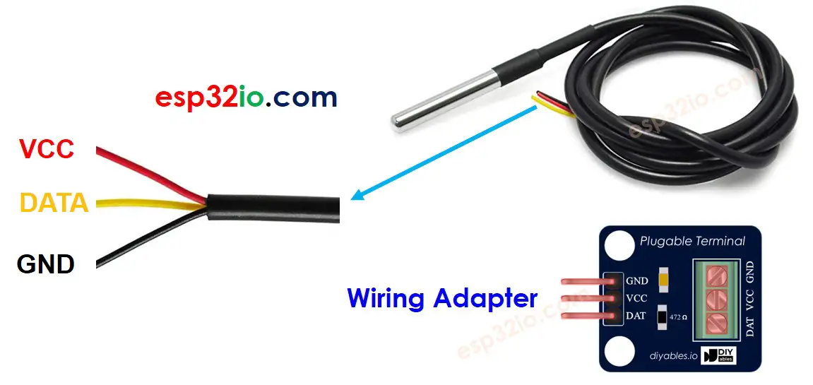
Connecting a DS18B20 temperature sensor with an Arduino often requires a pull-up resistor, which can be a hassle. However, some manufacturers have made the process simpler by offering a wiring adapter with a built-in pull-up resistor and a screw terminal block for easy connection.
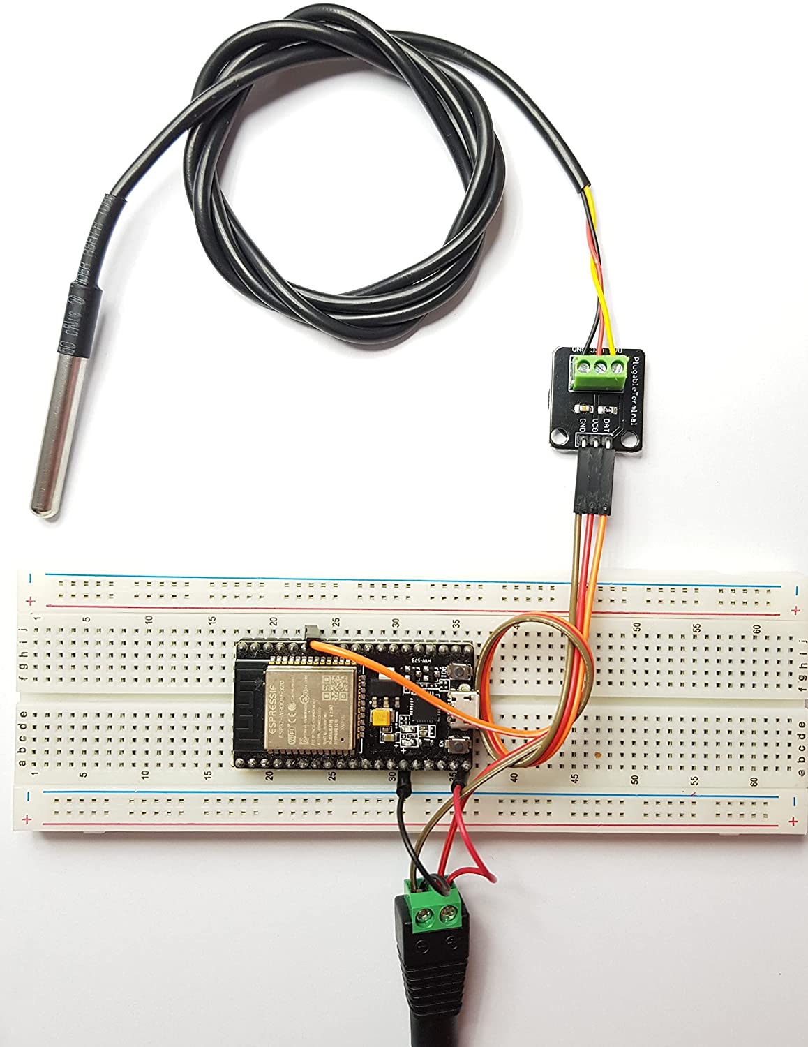
Wiring Diagram between DS18B20 Temperature Sensor and ESP32
- How to connect ESP32 and DS18B20 temperature sensor using breadboard.
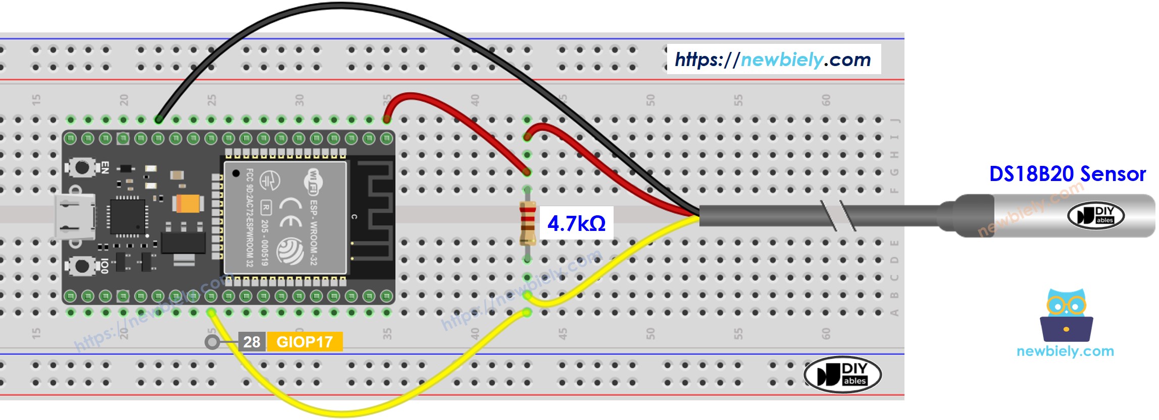
This image is created using Fritzing. Click to enlarge image
- How to connect ESP32 and DS18B20 temperature sensor using breadboard and adapter.
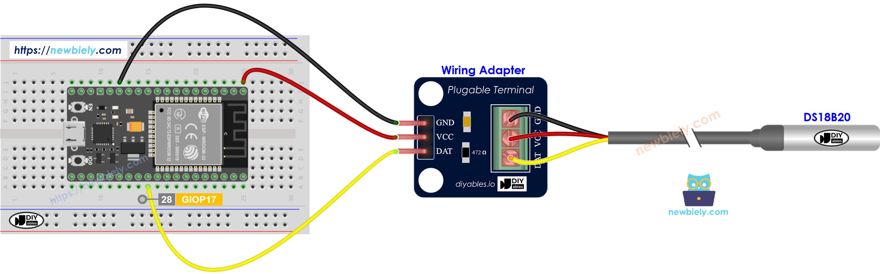
This image is created using Fritzing. Click to enlarge image
- How to connect ESP32 and temperature sensor using screw terminal block breakout board and adapter.
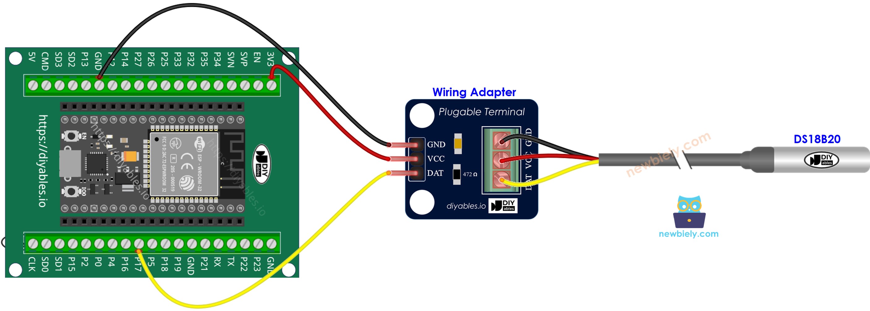
- Real wiring diagram with adapter
This image is created using Fritzing. Click to enlarge image
For ease of connection, it's advisable to purchase a DS18B20 sensor that comes with a wiring adapter equipped with a built-in resistor, eliminating the need for an additional resistor in the wiring.
If you're unfamiliar with how to supply power to the ESP32 and other components, you can find guidance in the following tutorial: The best way to Power ESP32 and sensors/displays.
ESP32 Code
Quick Instructions
- If this is the first time you use ESP32, see how to setup environment for ESP32 on Arduino IDE.
- Do the wiring as above image.
- Connect the ESP32 board to your PC via a micro USB cable
- Open Arduino IDE on your PC.
- Select the right ESP32 board (e.g. ESP32 Dev Module) and COM port.
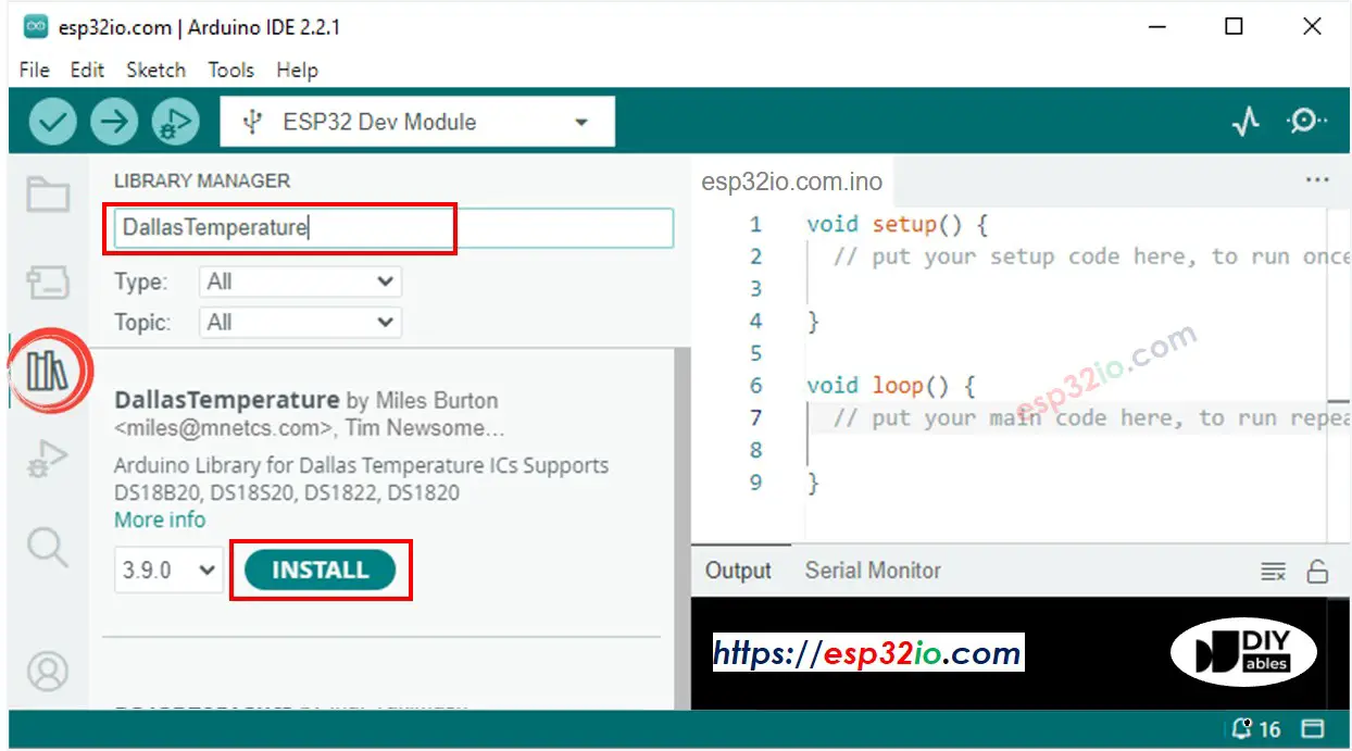
- Click to the Libraries icon on the left bar of the Arduino IDE.
- Search “DallasTemperature” on the search box, then look for the DallasTemperature library by Miles Burton.
- Click Install button to install DallasTemperature library.
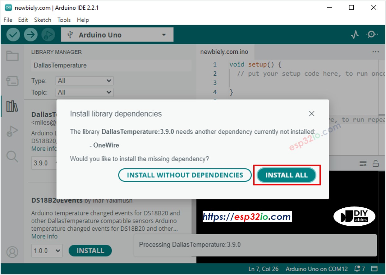
- You will be asked to install the dependency. Click Install All button to install OneWire library.
- Copy the above code and paste it to Arduino IDE.
- Compile and upload code to ESP32 board by clicking Upload button on Arduino IDE
- Make the sensor hotter or colder by gripping the DS18B20 temerature sensor on your hand, or embedding it on hot and cold water.
- See the result on Serial Monitor. It looks like the below:.
Video Tutorial
Making video is a time-consuming work. If the video tutorial is necessary for your learning, please let us know by subscribing to our YouTube channel , If the demand for video is high, we will make the video tutorial.