ESP32 RS232
In this tutorial, we are going to learn how to use RS232 communication with ESP32. In detail, we will learn:
- How to connect ESP32 to the TTL to RS232 module
- How to program ESP32 to read data from the TTL to RS232 module
- How to program ESP32 to send data to the TTL to RS232 module
Hardware Used In This Tutorial
Or you can buy the following kits:
| 1 | × | DIYables ESP32 Starter Kit (ESP32 included) | |
| 1 | × | DIYables Sensor Kit (18 sensors/displays) |
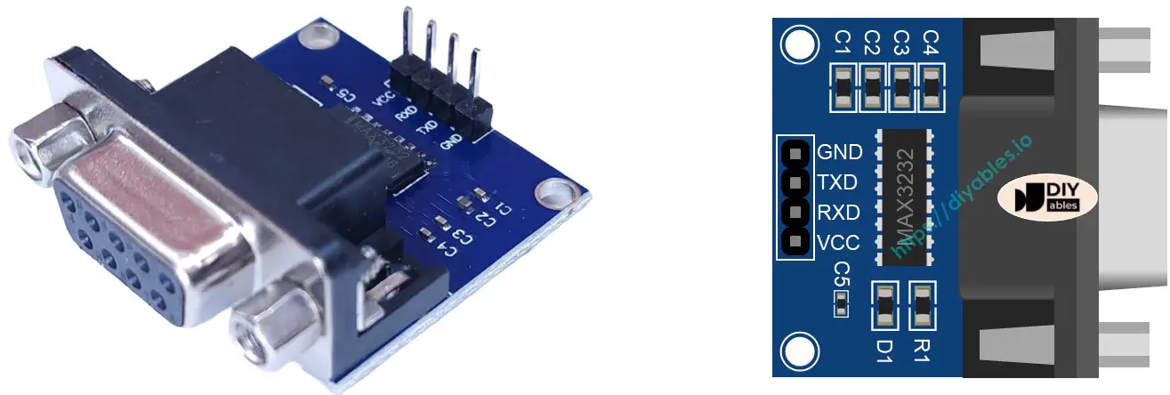
Introduction to TTL to RS232 Module
When you use the serial communication by using Serial.print(), Serial.read(), Serial.write() ... functions on ESP32, ESP32 output data to TX pin or read data come from RX pin. The signals on TX and RX pins are TTL level. This signal cannot go far. Therefore, when you want to use the serial communication via long distance, you need to converts the TTL signal to RS232, RS485, or RS422 signal.
The TTL to RS232 module converts TTL signal to RS232 signal, and vice versa.
Pinout
The RS232 to TTL module has two interfaces:
- The TTL interface (connnected to ESP32) includes 4 pins
- VCC pin: power pin, needs to be connected to VCC (5V/3.3V)
- GND pin: power pin, needs to be connected to GND (0V)
- RXD pin: data pin, needs to be connected a RX pin of ESP32
- TXD pin: data pin, needs to be connected a TX pin of ESP32
- The RS232 interface: DB9 female D-Sub connector, connect this to the serial device
Wiring Diagram
- How to connect ESP32 and RS232 to TTL module using breadboard
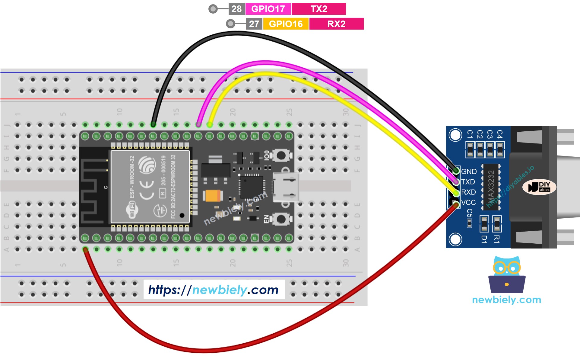
This image is created using Fritzing. Click to enlarge image
- How to connect ESP32 and RS232 to TTL module using screw terminal block breakout board
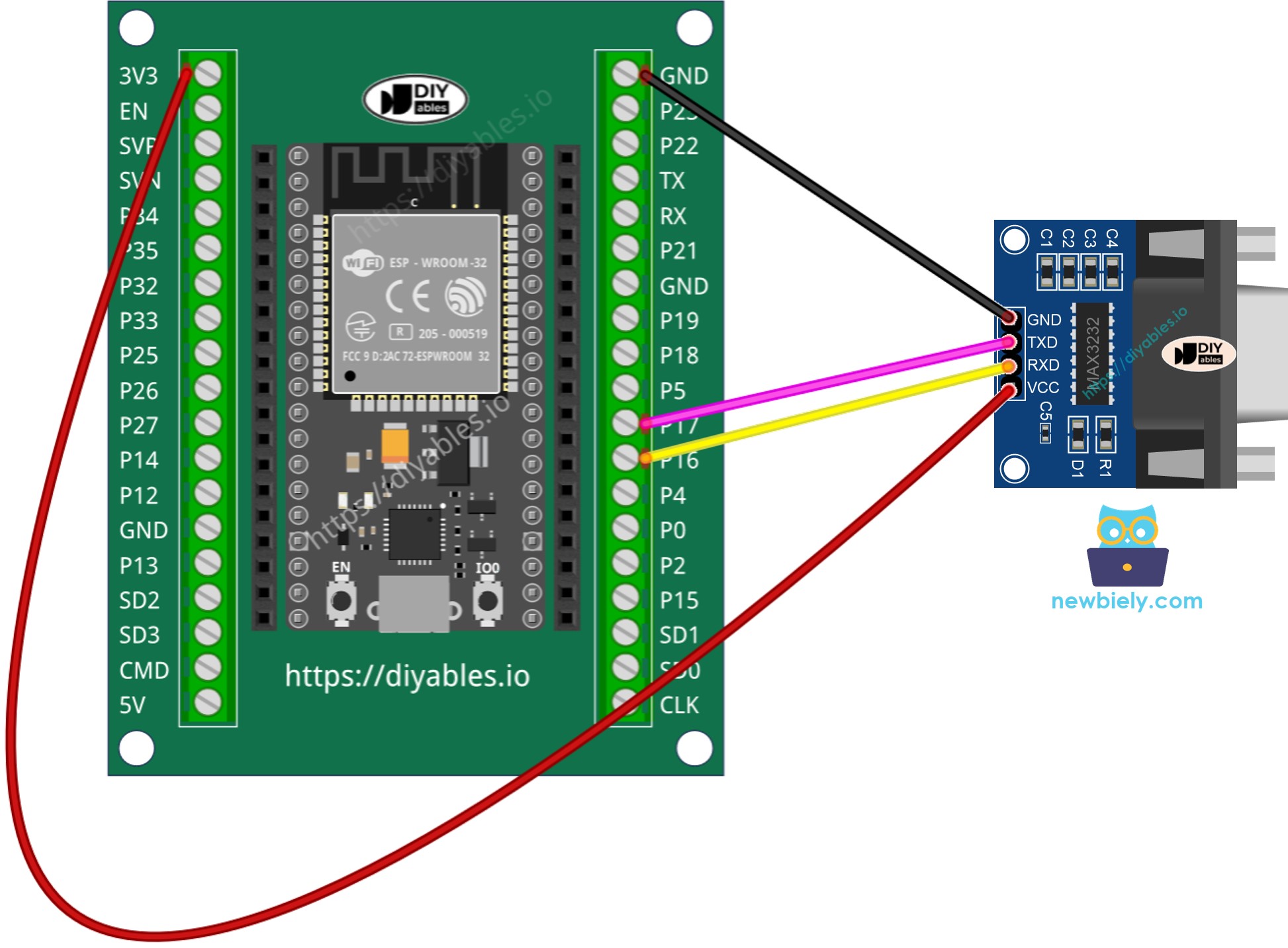
This image is created using Fritzing. Click to enlarge image
If you're unfamiliar with how to supply power to the ESP32 and other components, you can find guidance in the following tutorial: The best way to Power ESP32 and sensors/displays.
How To Program ESP32 to use the RS232 module
- If this is the first time you use ESP32, see how to setup environment for ESP32 on Arduini IDE.
- Initializes the Serial interface:
- To read data come from RS232, you can use the following functions:
- To write data to RS232, you can use the following functions:
- And more functions to use with RS232 in Serial reference
ESP32 Code for RS232
Testing
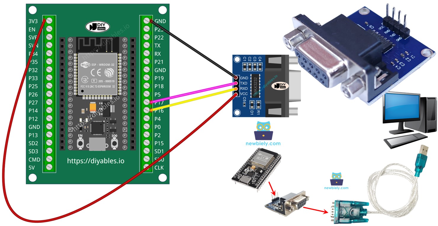
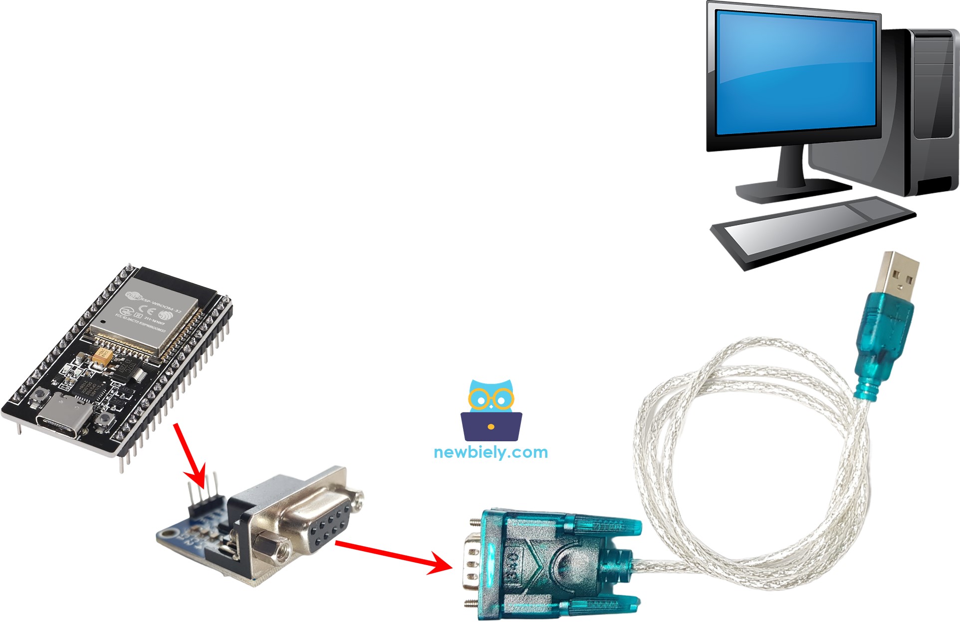
You can conduct a test by transmitting data between your PC and ESP32 via RS232 in both directions. Follow the steps outlined below:
- Connect the ESP32 to your PC using an RS232-to-USB cable, as illustrated in the image below:
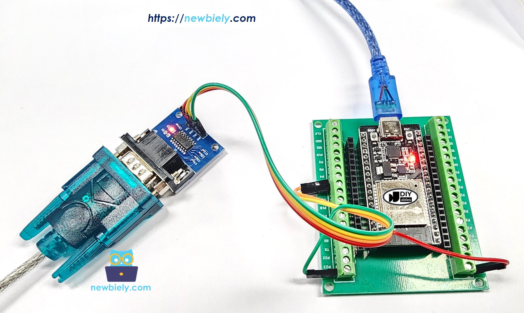
- The real connection to RS232-to-USB cable is shown as below:
- Open the Serial Terminal Program and configure the Serial parameters (COM port, baud rate, etc.).
- Enter some data in the Serial Terminal to transmit it to the ESP32.
- If the test is successful, you will observe the echoed data on the Serial Terminal.
Video Tutorial
Making video is a time-consuming work. If the video tutorial is necessary for your learning, please let us know by subscribing to our YouTube channel , If the demand for video is high, we will make the video tutorial.