ESP32 - Motion Sensor MP3 Player
In this guide, we will explore how to employ the ESP32, an HC-SR501 motion sensor, and an MP3 player to initiate the playback of a pre-recorded audio file when motion is detected. This project offers versatility and can be customized for various applications, such as delivering automated audio instructions or warnings whenever human presence is identified.
Hardware Used In This Tutorial
Or you can buy the following kits:
| 1 | × | DIYables ESP32 Starter Kit (ESP32 included) | |
| 1 | × | DIYables Sensor Kit (18 sensors/displays) |
Introduction to MP3 Player and Motion Sensor
Unfamiliar with MP3 player and motion sensor, including their pinouts, functionality, and programming? Explore comprehensive tutorials on these topics below:
Wiring Diagram
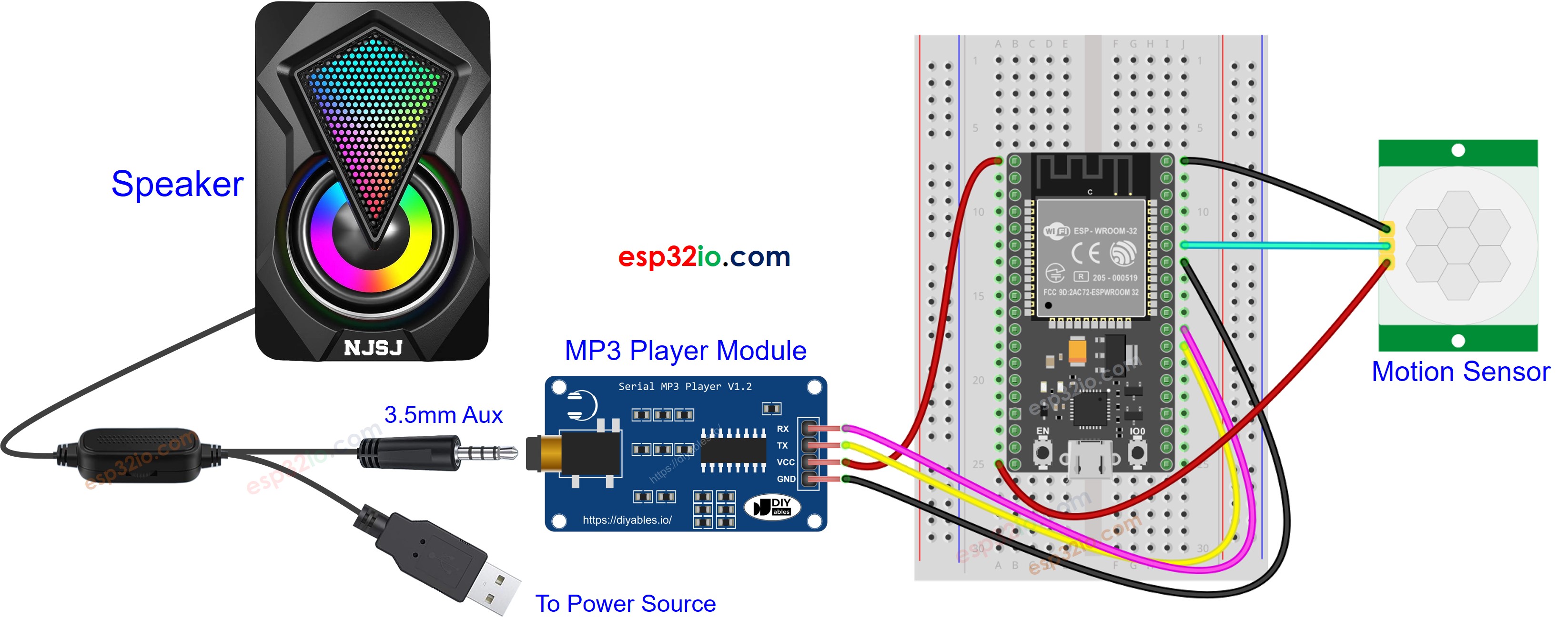
This image is created using Fritzing. Click to enlarge image
If you're unfamiliar with how to supply power to the ESP32 and other components, you can find guidance in the following tutorial: The best way to Power ESP32 and sensors/displays.
Preparation
- Pre-store the recorded mp3 file that we want to play to the micro SD Card.
- Insert the micro SD Card to the MP3 player module
- Connect the MP3 player module to ESP32
- Connect the speaker to the MP3 player module to a
- Connect the speaker to a power source.
- Connect the motion sensor to the ESP32.
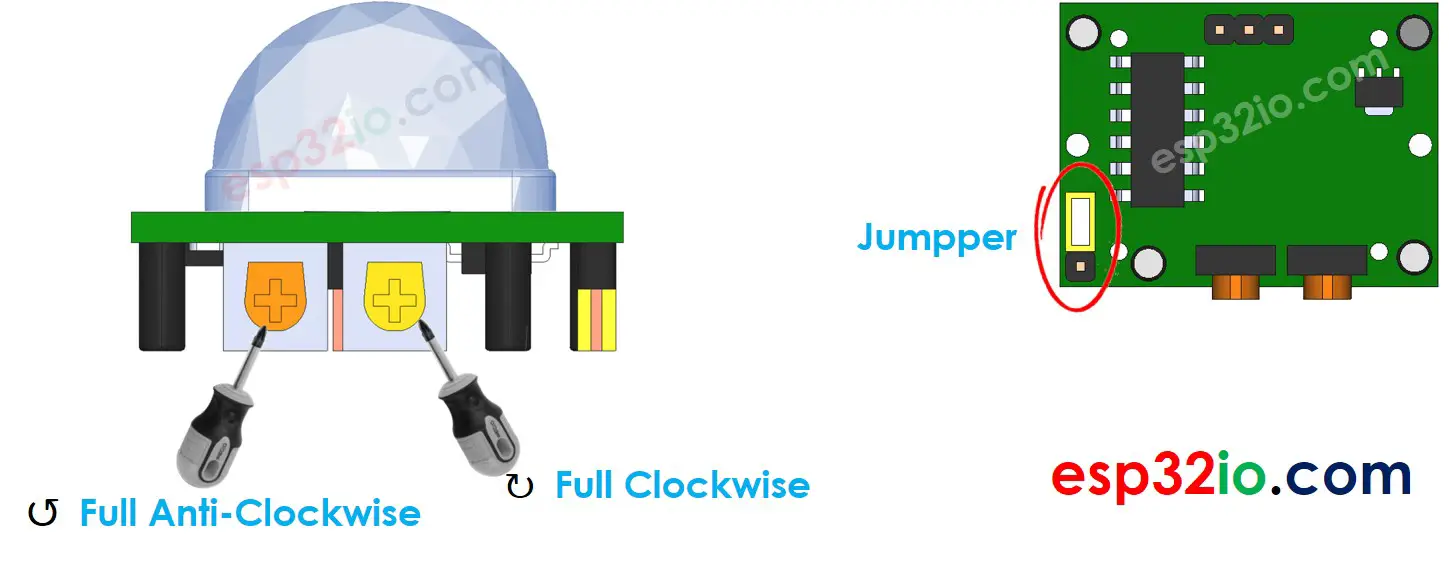
- Do setting for motion sensor as below table
| Time Delay Adjuster | Screw it in anti-clockwise direction fully. |
| Detection Range Adjuster | Screw it in clockwise direction fully. |
| Repeat Trigger Selector | Put jumper as shown on the image. |
ESP32 Code - Motion Sensor Controls MP3 Player
Quick Instructions
- If this is the first time you use ESP32, see how to setup environment for ESP32 on Arduino IDE.
- Do the wiring as above image.
- Connect the ESP32 board to your PC via a micro USB cable
- Open Arduino IDE on your PC.
- Select the right ESP32 board (e.g. ESP32 Dev Module) and COM port.
- Connect ESP32 to PC via USB cable
- Open Arduino IDE, select the right board and port
- Copy the above code and open with Arduino IDE
- Click Upload button on Arduino IDE to upload code to ESP32
- Move your hand in front of sensor
- Check out the audio from MP3 player
Video Tutorial
Making video is a time-consuming work. If the video tutorial is necessary for your learning, please let us know by subscribing to our YouTube channel , If the demand for video is high, we will make the video tutorial.