ESP32 - 74HC595 4-Digit 7-Segment Display
In this project, we will use an ESP32 to drive a 4-digit 7-segment display module with a 74HC595 shift register. The ESP32 offers Wi-Fi, Bluetooth, dual cores, and a generous set of GPIO pins - making it ideal for IoT projects that need a local display.
What we will build:
Wire the 74HC595 display module to the ESP32.
Display integers and floating-point numbers.
Show text and temperature with a degree symbol.
Present time in HH.MM format with a blinking separator.
This tutorial shows how to program the ESP32 using the Arduino language (C/C++) via the Arduino IDE. If you’d like to learn how to program the ESP32 with MicroPython, visit this ESP32 MicroPython - 74HC595 4-Digit 7-Segment Display tutorial.
Or you can buy the following kits:
Disclosure: Some of the links in this section are Amazon affiliate links, meaning we may earn a commission at no additional cost to you if you make a purchase through them. Additionally, some links direct you to products from our own brand,
DIYables .
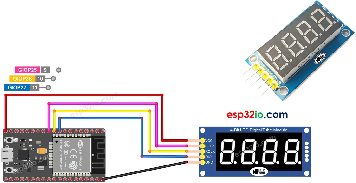
This module puts four 7-segment digits behind a 74HC595 shift register. Three data lines (SCLK, RCLK, DIO) carry the serial clock, latch, and data signals. The shift register converts serial input to parallel output for the LED segments. The library multiplexes through each digit at around 125 Hz, creating a steady display.
| Function | Pin | Description |
|---|
| SCLK (SH_CP) | Serial Clock | Clocks data bits into the register |
| RCLK (ST_CP) | Register Clock | Latches shifted data to the outputs |
| DIO (DS) | Data Input | Serial data line |
| VCC | Power | 3.3V or 5V |
| GND | Ground | Common ground |
Connect the display module to the ESP32:
SCLK to GPIO18
RCLK to GPIO17
DIO to GPIO16
VCC to 3.3V
GND to GND
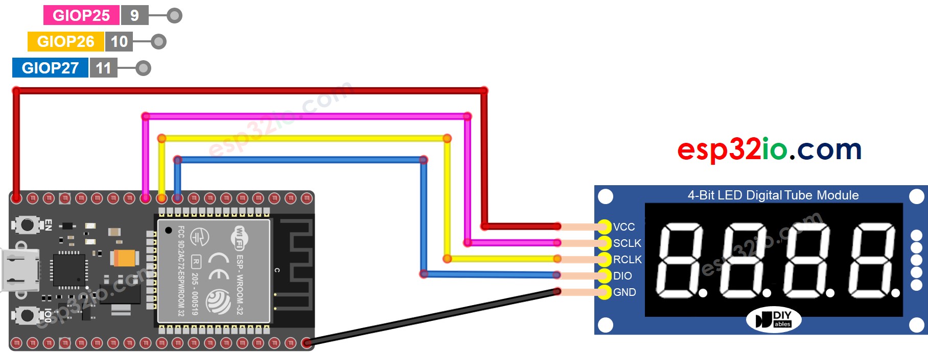
This image is created using Fritzing. Click to enlarge image
If you're unfamiliar with how to supply power to the ESP32 and other components, you can find guidance in the following tutorial: The best way to Power ESP32 and sensors/displays.
Connect the ESP32 board to your computer with a USB cable.
Open Arduino IDE and select ESP32 Dev Module as the board. Choose the correct port.
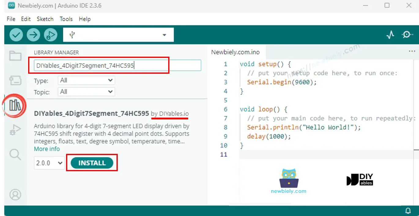
Click the Libraries icon on the left sidebar.
Search for "DIYables_4Digit7Segment_74HC595" and find the library by DIYables.
Click Install. Select version 2.0.0 or later.
No extra dependencies required - the library is self-contained.
A minimal sketch to get things running:
#include <DIYables_4Digit7Segment_74HC595.h>
#define SCLK_PIN 18
#define RCLK_PIN 17
#define DIO_PIN 16
DIYables_4Digit7Segment_74HC595 display(SCLK_PIN, RCLK_PIN, DIO_PIN);
void setup() {
display.begin();
display.print(1234);
}
void loop() {
display.loop();
}
begin() configures the GPIO pins as outputs. loop() drives the multiplexing and must run frequently. Set the display content with print(), printTemperature(), or printTime(). Use display.delay() instead of delay() to keep the display active during waits.
Cycles through integers and shows zero-padding.
#include <DIYables_4Digit7Segment_74HC595.h>
#define SCLK_PIN 18
#define RCLK_PIN 17
#define DIO_PIN 16
DIYables_4Digit7Segment_74HC595 display(SCLK_PIN, RCLK_PIN, DIO_PIN);
int numbers[] = {0, 42, 1234, -5, -123, 9999};
int numCount = 6;
int currentIndex = 0;
bool showZeroPad = false;
unsigned long lastChange = 0;
void setup() {
Serial.begin(9600);
display.begin();
Serial.println("4-Digit 7-Segment 74HC595 - Integer Example");
}
void loop() {
display.loop();
if (millis() - lastChange >= 2000) {
lastChange = millis();
if (!showZeroPad) {
display.print(numbers[currentIndex]);
Serial.print("Displaying: ");
Serial.println(numbers[currentIndex]);
currentIndex++;
if (currentIndex >= numCount) {
currentIndex = 0;
showZeroPad = true;
}
} else {
display.print(42, true);
Serial.println("Displaying: 0042 (zero-padded)");
showZeroPad = false;
}
}
}
Wire the display to the ESP32 as described above.
Connect the ESP32 to your computer via USB.
Open Arduino IDE, select the board and port, paste the code, and click Upload.
Open the Serial Monitor to see the output.
The display runs through 0, 42, 1234, -5, -123, 9999, then 0042 (zero-padded).
| Method | What It Does | Example |
|---|
| print(int) | Display an integer (-999 to 9999) | display.print(1234) |
| print(int, true) | Integer with leading zeros | display.print(42, true) |
| loop() | Refresh the display | display.loop() |
Floating-point numbers with auto and fixed decimals.
#include <DIYables_4Digit7Segment_74HC595.h>
#define SCLK_PIN 18
#define RCLK_PIN 17
#define DIO_PIN 16
DIYables_4Digit7Segment_74HC595 display(SCLK_PIN, RCLK_PIN, DIO_PIN);
void setup() {
Serial.begin(9600);
display.begin();
Serial.println("4-Digit 7-Segment 74HC595 - Float Example");
}
void loop() {
display.print(1.5);
Serial.println("Auto decimal: 1.5");
display.delay(2000);
display.print(12.34);
Serial.println("Auto decimal: 12.34");
display.delay(2000);
display.print(3.141);
Serial.println("Auto decimal: 3.141");
display.delay(2000);
display.print(-1.2);
Serial.println("Auto decimal: -1.20");
display.delay(2000);
display.print(0.5);
Serial.println("Auto decimal: 0.5");
display.delay(2000);
display.print(23.5, 1);
Serial.println("1 decimal place: 23.5");
display.delay(2000);
display.print(1.5, 2);
Serial.println("2 decimal places: 1.50");
display.delay(2000);
display.print(1.5, 2, true);
Serial.println("2 decimal places, zero-padded: 01.50");
display.delay(2000);
}
Shows auto-decimal floats, then 1 and 2 fixed decimal places, and zero-padded.
Text strings, degree symbol, and temperature output.
#include <DIYables_4Digit7Segment_74HC595.h>
#define SCLK_PIN 18
#define RCLK_PIN 17
#define DIO_PIN 16
DIYables_4Digit7Segment_74HC595 display(SCLK_PIN, RCLK_PIN, DIO_PIN);
const char* texts[] = {"HELP", "Hi", "COOL", "done"};
int textCount = 4;
int currentIndex = 0;
int phase = 0;
unsigned long lastChange = 0;
void setup() {
Serial.begin(9600);
display.begin();
Serial.println("4-Digit 7-Segment 74HC595 - Text and Degree Example");
}
void loop() {
display.loop();
if (millis() - lastChange >= 2000) {
lastChange = millis();
if (phase == 0) {
display.print(texts[currentIndex]);
Serial.print("Text: ");
Serial.println(texts[currentIndex]);
currentIndex++;
if (currentIndex >= textCount) {
currentIndex = 0;
phase = 1;
}
} else if (phase == 1) {
display.printTemperature(25, 'C');
Serial.println("Temperature: 25 C");
phase = 2;
} else if (phase == 2) {
display.printTemperature(72, 'F');
Serial.println("Temperature: 72 F");
phase = 3;
} else if (phase == 3) {
char degStr[5];
degStr[0] = '2';
degStr[1] = '5';
degStr[2] = DEGREE_CHAR;
degStr[3] = 'C';
degStr[4] = '\0';
display.print(degStr);
Serial.println("String with degree: 25 deg C");
phase = 4;
} else {
display.print("1.2.3.4");
Serial.println("Dots: 1.2.3.4");
phase = 0;
}
}
}
Shows "HELP", "Hi", "COOL", "done", temperatures, and inline dots.
Clock-style HH.MM with blinking separator.
#include <DIYables_4Digit7Segment_74HC595.h>
#define SCLK_PIN 18
#define RCLK_PIN 17
#define DIO_PIN 16
DIYables_4Digit7Segment_74HC595 display(SCLK_PIN, RCLK_PIN, DIO_PIN);
int hours = 12;
int minutes = 30;
bool colonOn = true;
unsigned long lastToggle = 0;
void setup() {
Serial.begin(9600);
display.begin();
Serial.println("4-Digit 7-Segment 74HC595 - Time Example");
Serial.println("Displaying 12:30 with blinking dot separator");
}
void loop() {
display.loop();
if (millis() - lastToggle >= 500) {
lastToggle = millis();
display.printTime(hours, minutes, colonOn);
colonOn = !colonOn;
}
}
Displays 12.30 with the dot blinking every 500ms.
Toggles the display on and off.
#include <DIYables_4Digit7Segment_74HC595.h>
#define SCLK_PIN 18
#define RCLK_PIN 17
#define DIO_PIN 16
DIYables_4Digit7Segment_74HC595 display(SCLK_PIN, RCLK_PIN, DIO_PIN);
int phase = 0;
int blinkCount = 0;
bool isOn = true;
unsigned long lastAction = 0;
unsigned long pauseUntil = 0;
void setup() {
Serial.begin(9600);
display.begin();
Serial.println("4-Digit 7-Segment 74HC595 - Blink Example");
display.print(1234);
Serial.println("Blinking: 1234");
}
void loop() {
display.loop();
unsigned long now = millis();
if (now < pauseUntil) return;
if (now - lastAction >= 300) {
lastAction = now;
if (isOn) {
display.off();
isOn = false;
} else {
display.on();
isOn = true;
blinkCount++;
if (blinkCount >= 5) {
blinkCount = 0;
pauseUntil = now + 1000;
phase++;
if (phase > 2) phase = 0;
switch (phase) {
case 0:
display.print(1234);
Serial.println("Blinking: 1234");
break;
case 1:
display.print(12.34);
Serial.println("Blinking: 12.34");
break;
case 2:
display.print("HELP");
Serial.println("Blinking: HELP");
break;
}
}
}
}
}
Blinks 1234, then 12.34, then "HELP" - five times each.
Display blank - Check VCC, GND, and GPIO connections. Verify pin numbers match your code.
Wrong characters - Default is common anode. Use false as the 4th argument for common cathode.
Flickering - Avoid delay(). Use display.delay() to keep the display refreshing.
The library is built using only Arduino standard APIs and works across all Arduino-compatible platforms including ESP32.