ESP32 - Door Lock System using Password

This tutorial instructs you how to use ESP32, Keypad and electromagnetic lock to make door lock system. Users will be ask for password via keypad. It the password is valid, the ESP32 controls electromagnetic lock to unlock the door. The tutorials also optionally adds an LCD for more convenience. The ESP32 code aslo supports multiple passwords.

Hardware Used In This Tutorial

1×ESP-WROOM-32 Dev Module
1×USB Cable Type-C
1×Keypad 3x4
1×Relay
1×Electromagnetic Lock
1×12V Power Adapter
1×Breadboard
1×Jumper Wires
1×(Optional) LCD I2C
1×(Optional) DC Power Jack
1×(Recommended) ESP32 Screw Terminal Adapter

Or you can buy the following sensor kits:

1×DIYables Sensor Kit (30 sensors/displays)
1×DIYables Sensor Kit (18 sensors/displays)
Disclosure: some of these links are affiliate links. We may earn a commission on your purchase at no extra cost to you. We appreciate it.

Introduction to Keypad and Electromagnetic Lock and LCD

We have specific tutorials about kypad, electromagnetic lock and LCD. Each tutorial contains detailed information and step-by-step instructions about hardware pinout, working principle, wiring connection to ESP32, ESP32 code... Learn more about them at the following links:

How check the password

  • A special key * is used to reset the password
  • A special key # is used to terminate the password input.
  • Every inputed key, except for * and # is appended in to a string.
  • When # key is pressed, the password input is complete. The ESP32 compares the inputed string with predefined passwords.
  • If the inputed password is vaild, unlock the door.

Wiring Diagram

ESP32 door lock system wiring diagram

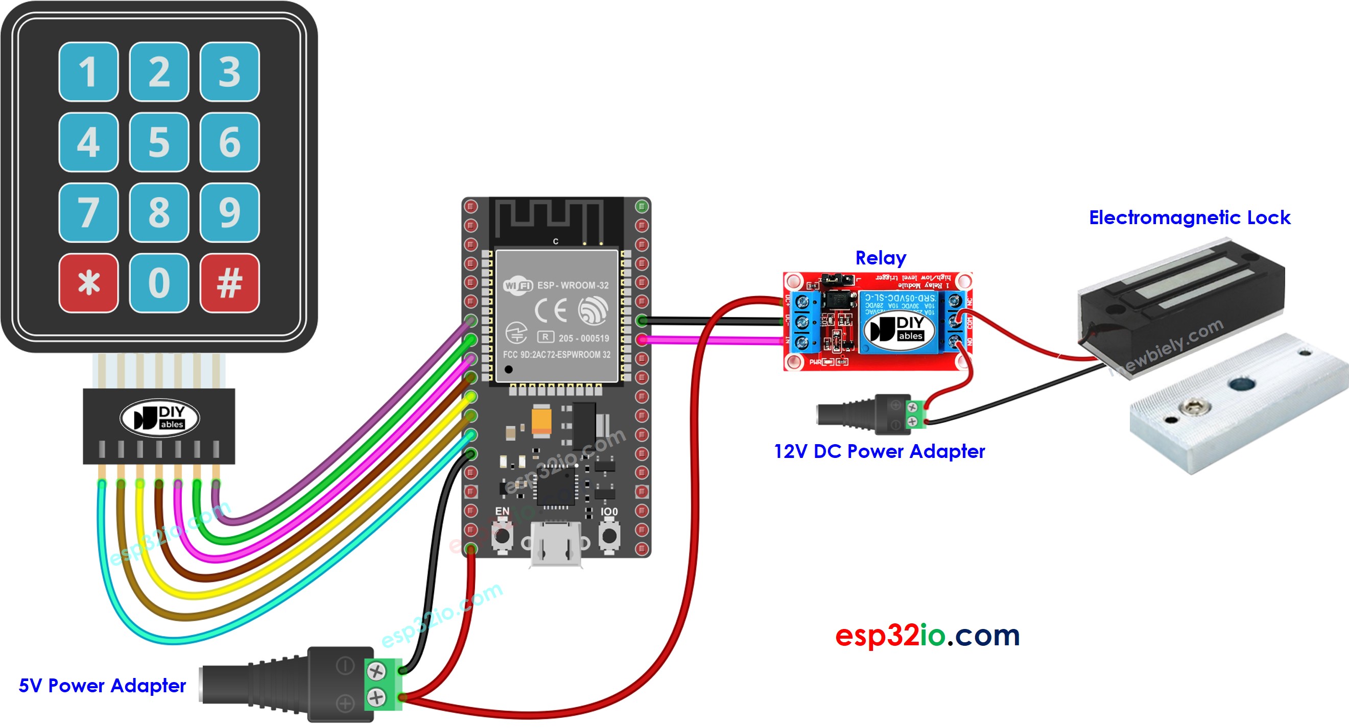
This image is created using Fritzing. Click to enlarge image

If you're unfamiliar with how to supply power to the ESP32 and other components, you can find guidance in the following tutorial: How to Power ESP32.

ESP32 Code - Door lock system with password using keypad, electromagnetic lock

/* * This ESP32 code is created by esp32io.com * * This ESP32 code is released in the public domain * * For more detail (instruction and wiring diagram), visit https://esp32io.com/tutorials/esp32-door-lock-system-using-password */ #include <Keypad.h> #define RELAY_PIN 19 // ESP32 pin GPIO19 connected to the relay #define ROW_NUM 4 // keypad four rows #define COLUMN_NUM 3 // keypad three columns char keys[ROW_NUM][COLUMN_NUM] = { {'1', '2', '3'}, {'4', '5', '6'}, {'7', '8', '9'}, {'*', '0', '#'} }; byte pin_rows[ROW_NUM] = {12, 14, 27, 26}; // ESP32 pin: GPIO12, GPIO14, GPIO27, GPIO26 connected to the row pins byte pin_column[COLUMN_NUM] = {25, 33, 32}; // ESP32 pin: GPIO25, GPIO33, GPIO32 connected to the column pins Keypad keypad = Keypad( makeKeymap(keys), pin_rows, pin_column, ROW_NUM, COLUMN_NUM ); const String password_1 = "1234"; // change your password here const String password_2 = "4444"; // change your password here const String password_3 = "55555"; // change your password here String input_password; void setup() { Serial.begin(9600); input_password.reserve(32); // maximum input characters is 32 pinMode(RELAY_PIN, OUTPUT); digitalWrite(RELAY_PIN, HIGH); // lock the door } void loop() { char key = keypad.getKey(); if (key) { Serial.println(key); if (key == '*') { input_password = ""; // reset the input password } else if (key == '#') { if (input_password == password_1 || input_password == password_2 || input_password == password_3) { Serial.println("Valid Password => unlock the door"); digitalWrite(RELAY_PIN, LOW); // unlock the door for 20 seconds delay(20000); digitalWrite(RELAY_PIN, HIGH); // lock the door } else { Serial.println("Invalid Password => Try again"); } input_password = ""; // reset the input password } else { input_password += key; // append new character to input password string } } }

Quick Instructions

  • If this is the first time you use ESP32, see how to setup environment for ESP32 on Arduino IDE.
  • Do the wiring as above image.
  • Connect the ESP32 board to your PC via a micro USB cable
  • Open Arduino IDE on your PC.
  • Select the right ESP32 board (e.g. ESP32 Dev Module) and COM port.
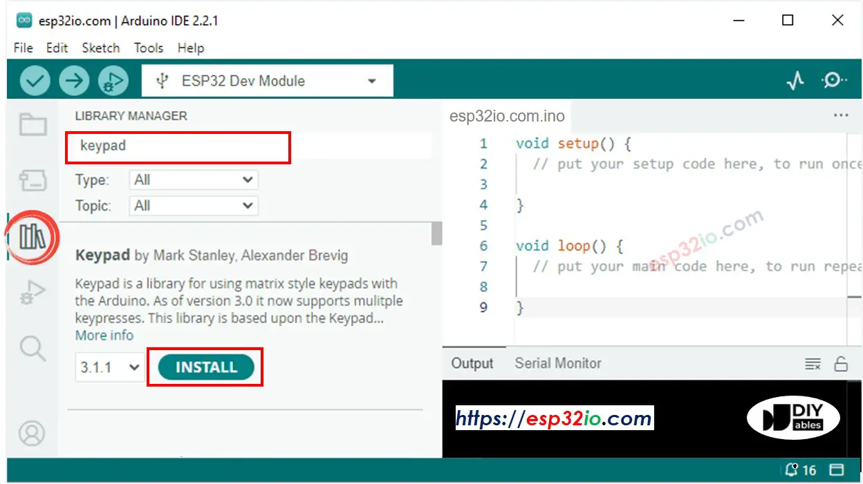
  • Click to the Libraries icon on the left bar of the Arduino IDE.
  • Type “keypad” on the search box, then look for the keypad library by Mark Stanley, Alexander Brevig
  • Click Install button to install keypad library.
ESP32 keypad library
  • Copy the above code and paste it to Arduino IDE.
  • Compile and upload code to ESP32 board by clicking Upload button on Arduino IDE
  • To simulate the electromagnet lock installed on the door, place the electromagnet near the armature plate.
  • Press 1111 keys and press #
  • Check the attraction force between electromagnet and armature plate.
  • Press 1234 keys and press #
  • Check the attraction force between electromagnet and armature plate.
  • See the result on Serial Monitor
COM6
Send
Invalid Password => Try again Valid Password => unlock the door
Autoscroll Show timestamp
Clear output
9600 baud  
Newline  

ESP32 Code - Door lock system with password using keypad, electromagnetic lock and LCD

The below code added LCD I2C to display the access status. For wiring with LCD, you can see in this tutorial Esp32 - LCD I2C tutorial

/* * This ESP32 code is created by esp32io.com * * This ESP32 code is released in the public domain * * For more detail (instruction and wiring diagram), visit https://esp32io.com/tutorials/esp32-door-lock-system-using-password */ #include <LiquidCrystal_I2C.h> #include <Keypad.h> #define RELAY_PIN 19 // ESP32 pin GPIO19 connected to the relay #define ROW_NUM 4 // keypad four rows #define COLUMN_NUM 3 // keypad three columns char keys[ROW_NUM][COLUMN_NUM] = { {'1', '2', '3'}, {'4', '5', '6'}, {'7', '8', '9'}, {'*', '0', '#'} }; byte pin_rows[ROW_NUM] = {12, 14, 27, 26}; // ESP32 pin: GPIO12, GPIO14, GPIO27, GPIO26 connected to the row pins byte pin_column[COLUMN_NUM] = {25, 33, 32}; // ESP32 pin: GPIO25, GPIO33, GPIO32 connected to the column pins Keypad keypad = Keypad( makeKeymap(keys), pin_rows, pin_column, ROW_NUM, COLUMN_NUM ); const String password_1 = "1234"; // change your password here const String password_2 = "4444"; // change your password here const String password_3 = "55555"; // change your password here String input_password; LiquidCrystal_I2C lcd(0x27, 16, 2); // I2C address 0x27 (from DIYables LCD), 16 column and 2 rows void setup() { Serial.begin(9600); input_password.reserve(32); // maximum input characters is 32 pinMode(RELAY_PIN, OUTPUT); digitalWrite(RELAY_PIN, HIGH); lcd.init(); // initialize the lcd lcd.backlight(); } void loop() { char key = keypad.getKey(); if (key) { Serial.println(key); if (key == '*') { input_password = ""; // reset the input password lcd.clear(); } else if (key == '#') { lcd.clear(); if (input_password == password_1 || input_password == password_2 || input_password == password_3) { Serial.println("Valid Password => unlock the door"); lcd.setCursor(0, 0); lcd.print("CORRECT!"); lcd.setCursor(0, 1); lcd.print("DOOR UNLOCKED!"); digitalWrite(RELAY_PIN, LOW); // unlock the door for 20 seconds delay(20000); digitalWrite(RELAY_PIN, HIGH); // lock the door } else { Serial.println("Invalid Password => Try again"); lcd.setCursor(0, 0); lcd.print("INCORRECT!"); lcd.setCursor(0, 1); lcd.print("ACCESS DENIED!"); } input_password = ""; // reset the input password } else { if (input_password.length() == 0) { lcd.clear(); } input_password += key; // append new character to input password string lcd.setCursor(input_password.length(), 0); // move cursor to new position lcd.print('*'); // print * key as hiden character } } }

※ NOTE THAT:

The LCD I2C address can be different from each manufacturer. In the code, we used address of 0x27 that is specified by DIYables manufacturer

Video Tutorial

Making video is a time-consuming work. If the video tutorial is necessary for your learning, please let us know by subscribing to our YouTube channel , If the demand for video is high, we will make the video tutorial.

※ OUR MESSAGES