ESP32 - Electromagnetic Lock
The electromagnetic lock (also known as magnetic lock, maglock, or EM lock) is an important component of the door lock system. This tutorial instructs you how to use ESP32 to control the electromagnetic lock.
This tutorial shows how to program the ESP32 using the Arduino language (C/C++) via the Arduino IDE. If you’d like to learn how to program the ESP32 with MicroPython, visit this ESP32 MicroPython - Electromagnetic Lock tutorial.
Hardware Used In This Tutorial
Or you can buy the following kits:
| 1 | × | DIYables ESP32 Starter Kit (ESP32 included) | |
| 1 | × | DIYables Sensor Kit (18 sensors/displays) |
Introduction to Electromagnetic Lock
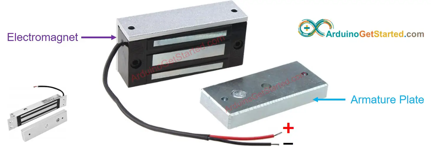
Electromagnetic Lock Pinout
The electromagnetic Lock is composed of two components:
- Armature plate: this part is attached on the moving part of the door
- Electromagnet: this part is attached on the door frame. it has two wires, which are connected to power source.
When the door is closed, two components are in contact with each other.
How Electromagnetic Lock Works
- When the electromagnet is powered ⇒ the electromagnet attracts to armature plate ⇒ lock
- When the electromagnet is NOT powered ⇒ the electromagnet does NOT attract to armature plate ⇒ unlock
The electromagnetic lock uses high voltage (12V, 24V or 48V...) power supply. Therefore, we need to use a relay in between the electromagnetic lock and ESP32 pin. See ESP32 - Relay tutorial.
If we connect the electromagnetic lock to a relay in normally open mode and use an ESP32 pin to control the relay:
- When the ESP32 pin is LOW ⇒ the relay is open ⇒ door is unlocked
- When the ESP32 pin is HIGH ⇒ the relay is closed ⇒ door is locked
Wiring Diagram between Electromagnetic Lock and ES32
- How to connect ESP32 and electromagnetic lock using breadboard (powered via USB cable)
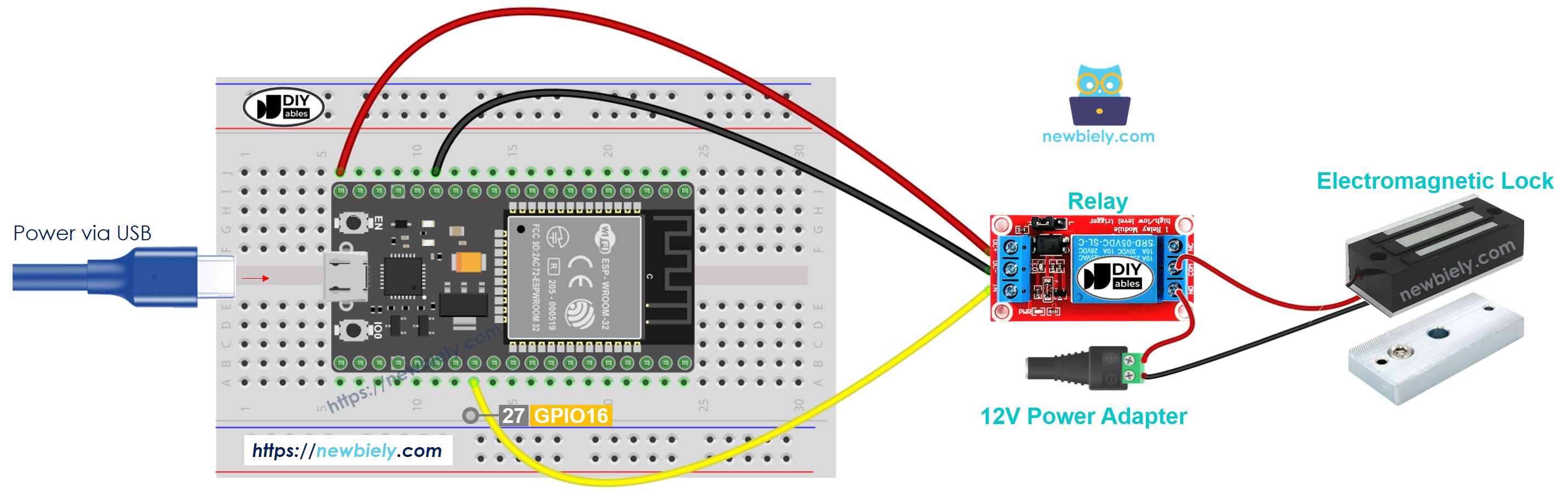
This image is created using Fritzing. Click to enlarge image
- How to connect ESP32 and electromagnetic lock using breadboard (powered via Vin pin)
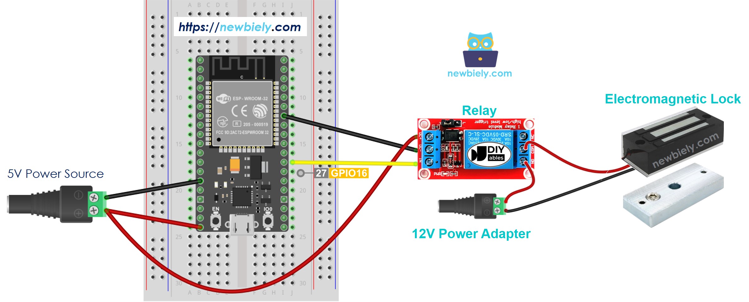
This image is created using Fritzing. Click to enlarge image
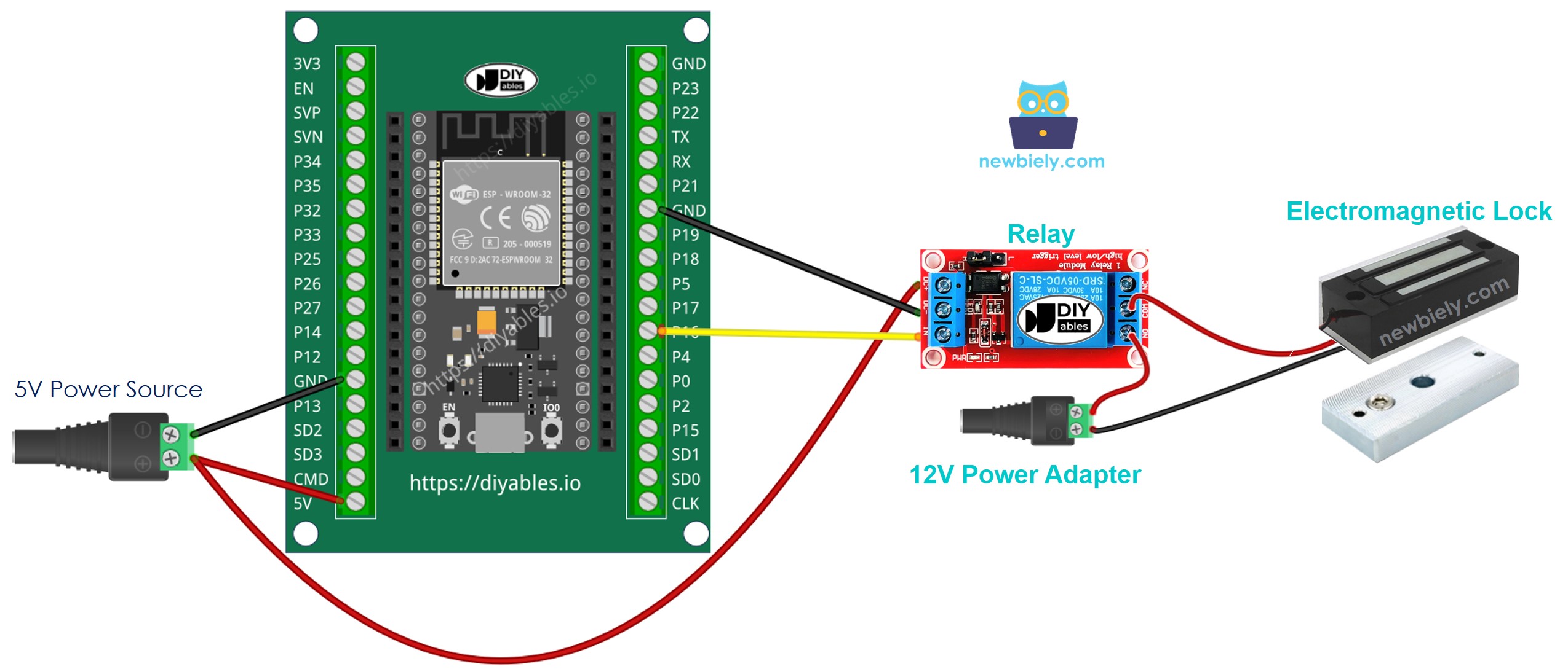
- How to connect ESP32 and electromagnetic lock using screw terminal block breakout board (powered via USB cable)
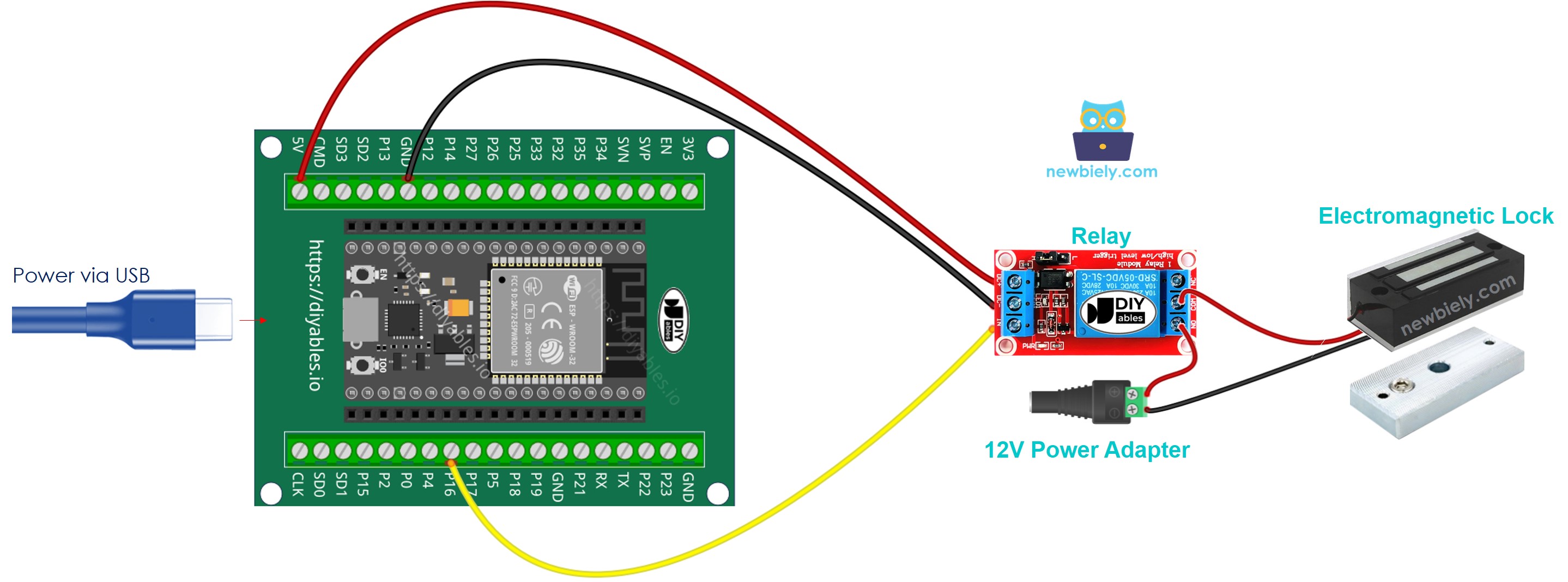
- How to connect ESP32 and electromagnetic lock using screw terminal block breakout board (powered via Vin pin)
If you're unfamiliar with how to supply power to the ESP32 and other components, you can find guidance in the following tutorial: The best way to Power ESP32 and sensors/displays.
ESP32 Code
The below code lock/unlock the door every 5 seconds
Quick Instructions
- If this is the first time you use ESP32, see how to setup environment for ESP32 on Arduino IDE.
- Copy the above code and paste it to Arduino IDE.
- Compile and upload code to ESP32 board by clicking Upload button on Arduino IDE
- Put the armature plate close to electromagnet.
- See the attraction between armature plate and electromagnet.
Video Tutorial
Making video is a time-consuming work. If the video tutorial is necessary for your learning, please let us know by subscribing to our YouTube channel , If the demand for video is high, we will make the video tutorial.