ESP32 - Sound Sensor - Relay
In this tutorial, we'll explore how to utilize the sound sensor to control relay. Specifically, we'll delve into two exciting applications:
- Sound switch: When sound is detected (e.g knock), the ESP32 toggles the relay, turning it on if it's off, and off if it's on.
- Sound-activated relay: Upon detecting sound, the ESP32 turns on the relay for a specific period of time.
By connecting relay to light bulb, led strip, motor or actuator... We can use the sound sensor to control light bulb, led strip, motor or actuator...
Hardware Used In This Tutorial
Or you can buy the following kits:
| 1 | × | DIYables ESP32 Starter Kit (ESP32 included) | |
| 1 | × | DIYables Sensor Kit (18 sensors/displays) |
Introduction to Relay and Sound Sensor
If you do not know about relay and sound sensor (pinout, how it works, how to program ...), learn about them in the following tutorials:
Wiring Diagram
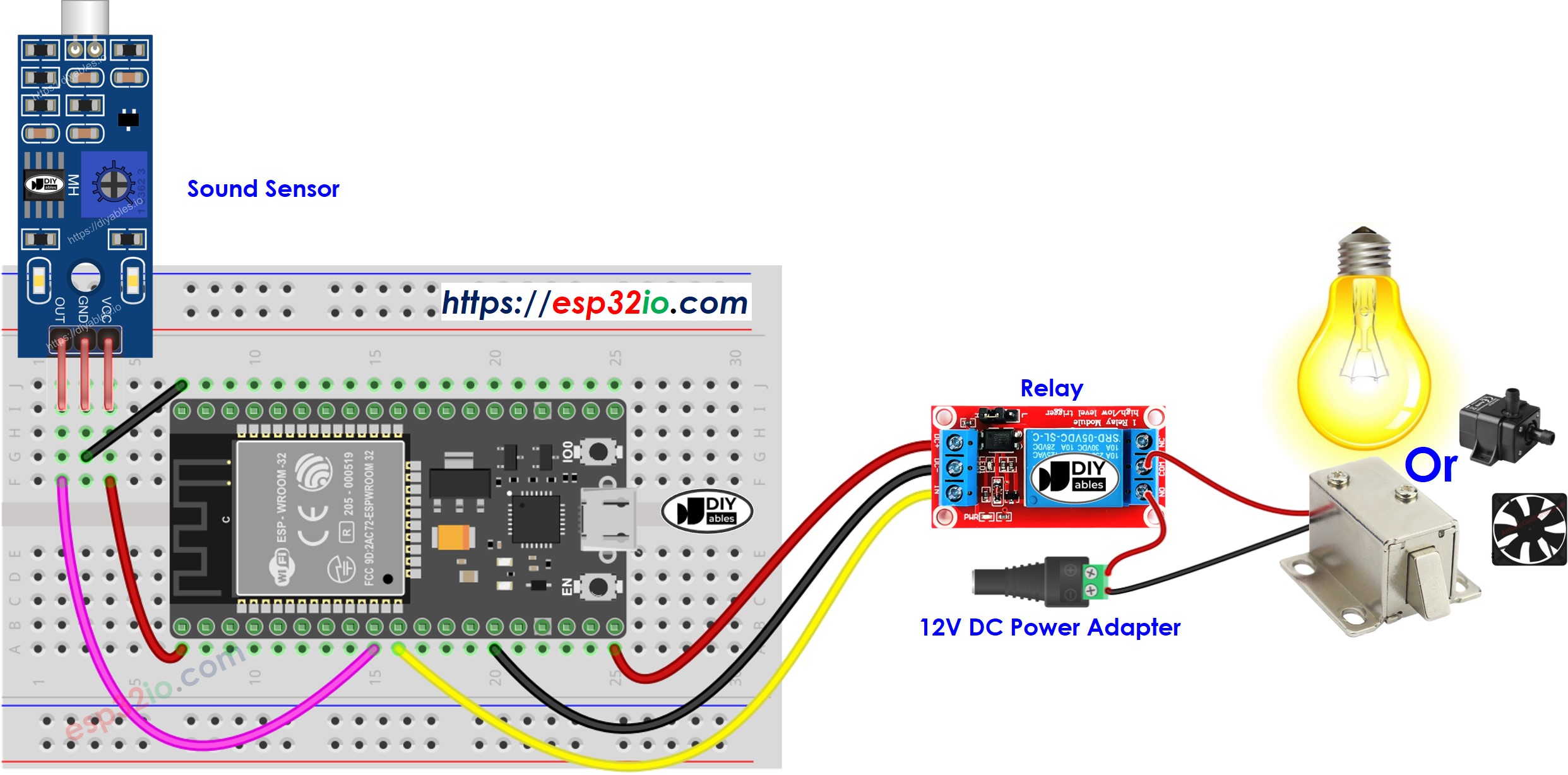
This image is created using Fritzing. Click to enlarge image
If you're unfamiliar with how to supply power to the ESP32 and other components, you can find guidance in the following tutorial: The best way to Power ESP32 and sensors/displays.
ESP32 Code - Sound Switch toggles Relay
The below code toggles the state of relay each time the sound is detected.
Quick Instructions
- If this is the first time you use ESP32, see how to setup environment for ESP32 on Arduino IDE.
- Do the wiring as above image.
- Connect the ESP32 board to your PC via a micro USB cable
- Open Arduino IDE on your PC.
- Select the right ESP32 board (e.g. ESP32 Dev Module) and COM port.
- Connect ESP32 to PC via USB cable
- Open Arduino IDE, select the right board and port
- Copy the above code and open with Arduino IDE
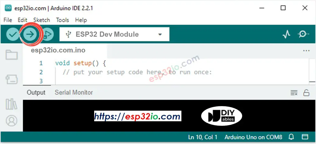
- Click Upload button on Arduino IDE to upload code to ESP32
- Clap your hand in front of the sound sensor
- See the change of the relay's state
Code Explanation
Read the line-by-line explanation in comment lines of source code!
ESP32 Code - Sound-activated Relay for a period of time
The below code turns on the relay for a period of time when the sound is detected. After the period of time, the relay is turned off.
Please take note that the code mentioned above utilizes the delay() function for simplicity. However, if you incorporate additional code, it may get blocked during the delay time. To address this, the following code implements a non-blocking approach using the ezLED library. Behind the scenes, the ezLED library employs the millis() function instead of delay to prevent blocking.
Quick Instructions
- If this is the first time you use ESP32, see how to setup environment for ESP32 on Arduino IDE.
- Do the wiring as above image.
- Connect the ESP32 board to your PC via a micro USB cable
- Open Arduino IDE on your PC.
- Select the right ESP32 board (e.g. ESP32 Dev Module) and COM port.
- Connect ESP32 to PC via USB cable
- Open Arduino IDE, select the right board and port
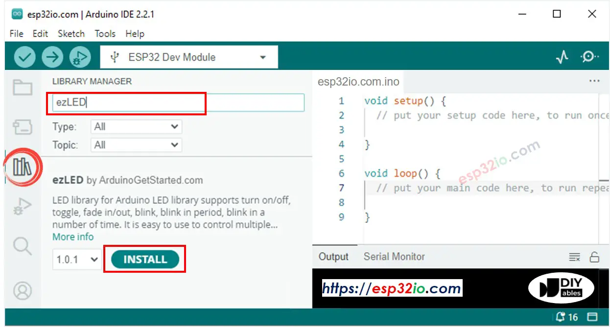
- Click to the Libraries icon on the left bar of the Arduino IDE.
- Search “ezLED”, then find the led library by ArduinoGetStarted
- Click Install button to install ezLED library.
- Copy the above code and open with Arduino IDE
- Click Upload button on Arduino IDE to upload code to ESP32
- Clap your hand in front of the sound sensor
- See the change of the relay's state
Video Tutorial
Making video is a time-consuming work. If the video tutorial is necessary for your learning, please let us know by subscribing to our YouTube channel , If the demand for video is high, we will make the video tutorial.