ESP32 - Servo Motor
This tutorial instructs you how to use ESP32 to control a servo motor.
This tutorial shows how to program the ESP32 using the Arduino language (C/C++) via the Arduino IDE. If you’d like to learn how to program the ESP32 with MicroPython, visit this ESP32 MicroPython - Servo Motor tutorial.
Hardware Used In This Tutorial
Or you can buy the following kits:
| 1 | × | DIYables ESP32 Starter Kit (ESP32 included) | |
| 1 | × | DIYables Sensor Kit (18 sensors/displays) |
Buy Note: In case of using multiple servo motors, it is recommended to use the PCA9685 16 Channel PWM Servo Driver Module to save MCU pins and simplify the wiring process.
Introduction to Servo Motor
The standard servo motor is a motor that can rotate between 0° and 180°.
Servo Motor Pinout
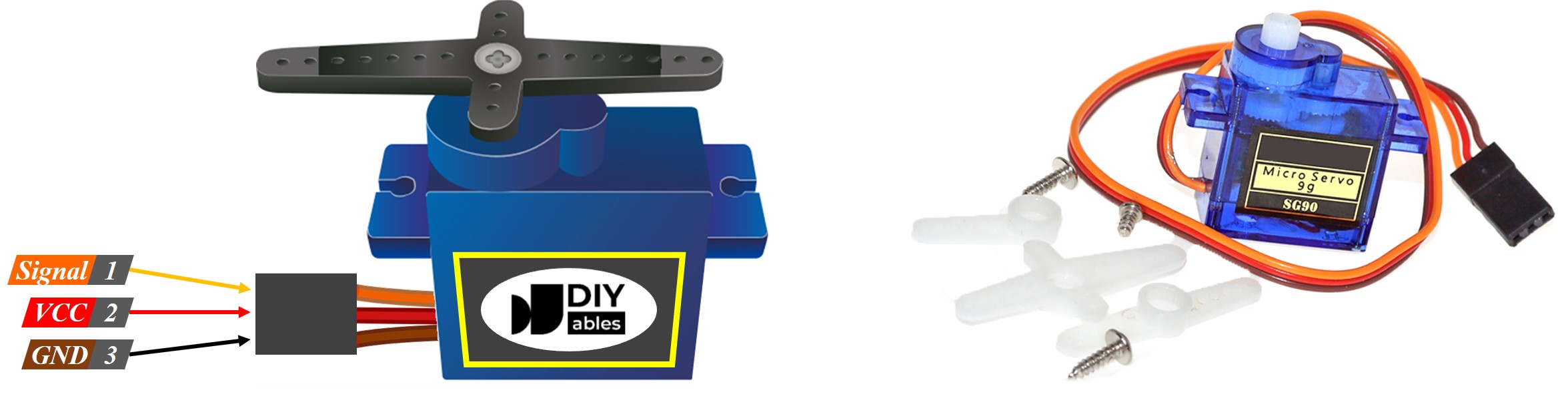
The servo motor has three pins:
- GND pin: (brown or black) connects this pin to GND (0V)
- VCC pin: (red) connects this pin to VCC (5V)
- Signal pin: (yellow or orange) receives the PWM control signal from an ESP32's pin.
How Servo Motor Works
Wiring Diagram between Servo Motor and ESP32
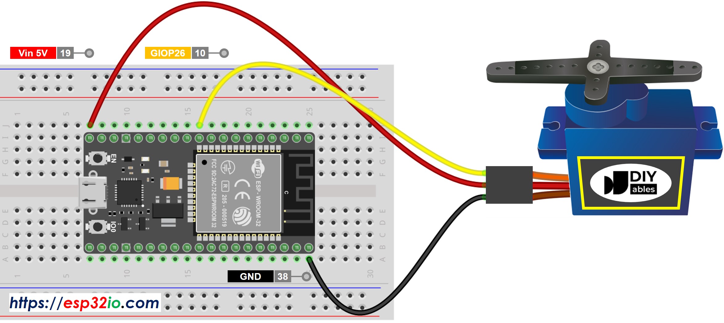
This image is created using Fritzing. Click to enlarge image
For the sake of simplicity, the above wiring diagram is used for the testing or learning purposes, and for small-torque servo motor. In practice, we highly recommend using the external power supply for the servo motor. The below wiring diagram shows how to connect servo motor to an external power source.
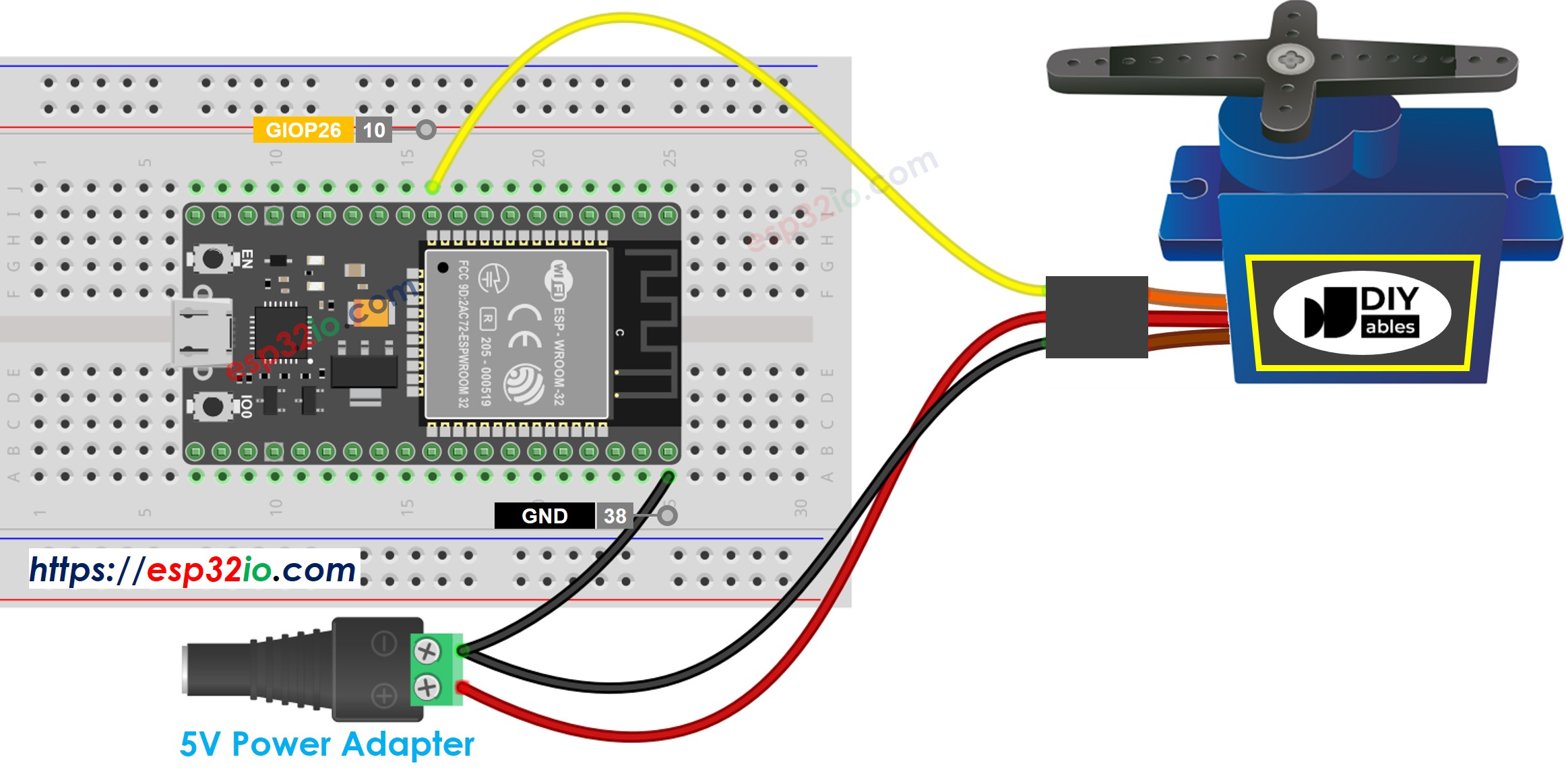
This image is created using Fritzing. Click to enlarge image
The below show a real wiring between servo motor and ESP32.
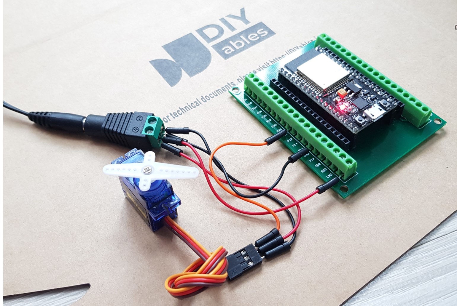
If you're unfamiliar with how to supply power to the ESP32 and other components, you can find guidance in the following tutorial: The best way to Power ESP32 and sensors/displays.
ESP32 Code
Quick Instructions
- If this is the first time you use ESP32, see how to setup environment for ESP32 on Arduino IDE.
- Do the wiring as above image.
- Connect the ESP32 board to your PC via a micro USB cable
- Open Arduino IDE on your PC.
- Select the right ESP32 board (e.g. ESP32 Dev Module) and COM port.
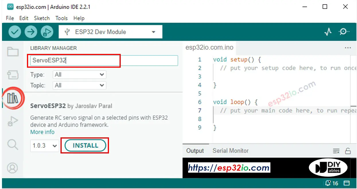
- Click to the Libraries icon on the left bar of the Arduino IDE.
- Type ESP32Servo on the search box, then look for the servo library by Kevin Harrington,John K. Bennett.
- Click Install button to install servo motor library for ESP32.
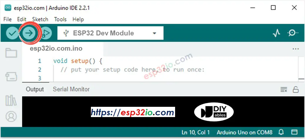
- Copy the above code and paste it to Arduino IDE.
- Compile and upload code to ESP32 board by clicking Upload button on Arduino IDE
- See the result: Servo motor rotates slowly about 180° in clockwise and counter-clockwise direction
Line-by-line Code Explanation
The above ESP32 code contains line-by-line explanation. Please read the comments in the code!
How to Control Speed of Servo Motor
Video Tutorial
Making video is a time-consuming work. If the video tutorial is necessary for your learning, please let us know by subscribing to our YouTube channel , If the demand for video is high, we will make the video tutorial.
The instruction and source code for the above video available at how to control servo motor via web tutotiral