ESP32 - Actuator
This tutorial instructs you how to use ESP32 to control a linear actuator. In detail, we will learn:
- How linear actuator works
- How to make linear actuator extend or retract.
- How to control a linear actuator using L298N driver.
- How to control the speed of a linear actuator.
This tutorial is for linear actuator without feedback. If you want to learn about linear actuator with feedback, see this ESP32 - Actuator with Feedback tutorial.
This tutorial shows how to program the ESP32 using the Arduino language (C/C++) via the Arduino IDE. If you’d like to learn how to program the ESP32 with MicroPython, visit this ESP32 MicroPython - Actuator tutorial.
Hardware Used In This Tutorial
Or you can buy the following kits:
| 1 | × | DIYables ESP32 Starter Kit (ESP32 included) | |
| 1 | × | DIYables Sensor Kit (18 sensors/displays) |
Introduction to Linear Actuator
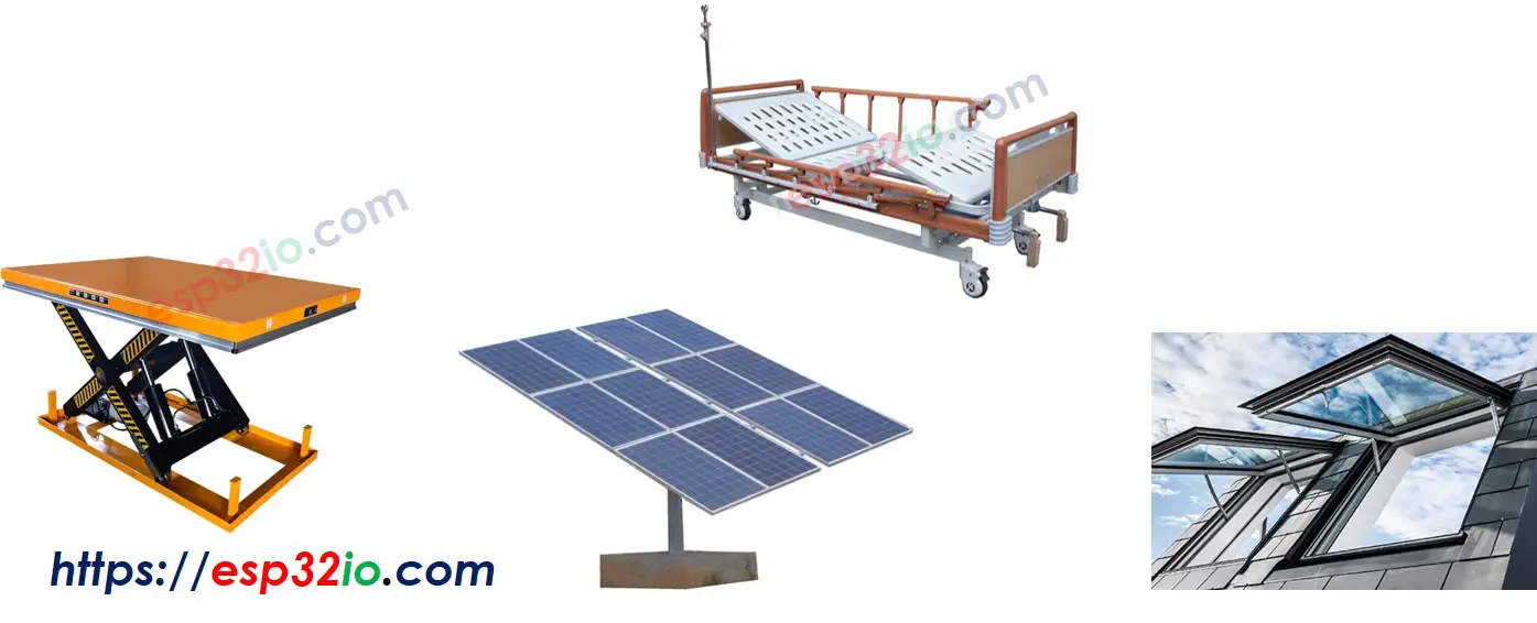
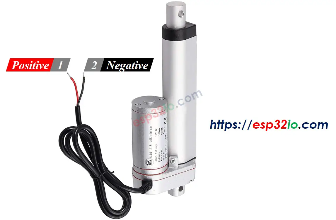
Linear Actuator Pinout
Linear Actuator has two wires:
- Positive wire: usually red
- Negative wire: usually black
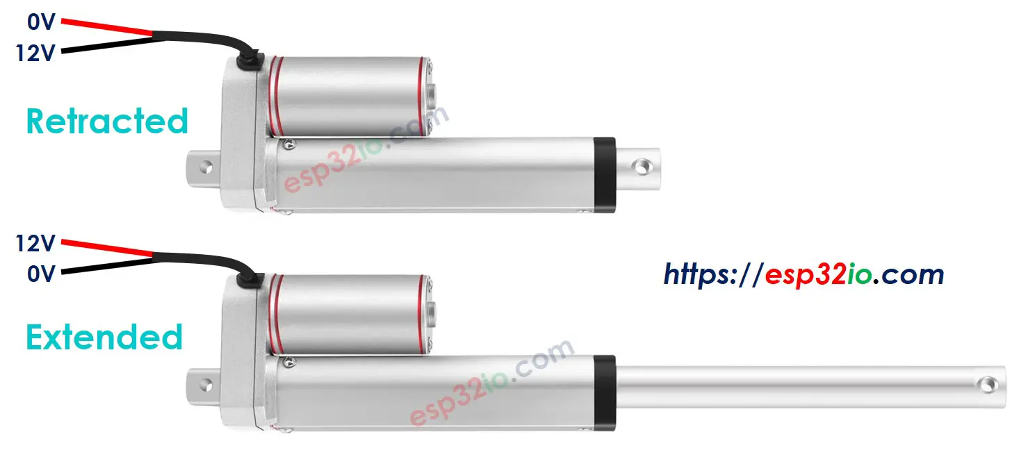
How It Works
When you buy a linear actuator, you need to know what voltage linear actuator works. Let's take a 12V linear actuator as an example.
When you power the 12V linear actuator by a 12V power source:
- 12V and GND to the positive wire and negative wire, respectively: the linear actuator full-speed extends until it reaches the limit.
- 12V and GND to the negative wire and positive wire, respectively: the linear actuator full-speed retracts until it reaches the limit.
While extending or retracting, if we stop power to the actuator (GND to both positive and negative wire), the actuator stops extending/retracting
※ NOTE THAT:
For DC motor, servo motor, and stepper motor without gearing, when carrying a load, if we stop powering, they cannot keep the position. Unlike these motors, the actuator can keep the position even when stopping powering while carrying a load.
If we provide power to linear actuators below 12V, the linear actuator still extends/retracts but not at maximum speed. It means if we change the voltage of the power supply, we can change the speed of the linear actuator. However, this method is not used in practice because of the difficulty in controlling the voltage of the power source. Instead, we fix the voltage of the power source and control the speed of the linear actuator via a PWM signal. The more duty cycle the PWM is, the higher speed the linear actuator extends/retracts.
How to control a linear actuator using ESP32
Controlling a linear actuator includes:
- Extends the linear actuator at maximum speed.
- Retracts the linear actuator at maximum speed.
- (optional) controls the extending/retracting speed
ESP32 can generate the signal to control the linear actuator. However, this signal has low voltage and current, We cannot use it to control the linear actuator. We need to use a hardware driver in between ESP32 and linear actuator. The driver does two works:
- Amplify the control signal from ESP32 (current and voltage)
- Receive the another control signal from ESP32 to swap pole of power supply → for direction control.
※ NOTE THAT:
- This tutorial can be applied to all linear actuators. 12V linear actuator is just an example.
- When you controls 5V linear actuator, although ESP32 pin outputs 5V (the same as linear actuator voltage), you still needs a driver in between ESP32 and linear actuator because the ESP32 pin does not provide enough the current for linear actuator.
There are many kinds of the chip, modules (e.g. L293D, L298N) can be used as linear actuator drivers. In this tutorial, we will use the L298N driver.
※ NOTE THAT:
You can also use relays as a driver. However it requires 4 relays to control a single linear actuator (both extend/retract)
Introduction to L298N Driver
L298N Driver can be used to control linear actuator, DC motor and stepper motor. In this tutorial, we learn how to use it to control the linear actuator.

L298N Driver Pinout
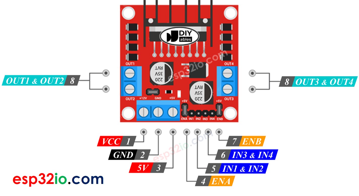
L298N Driver has two channels, called channel A and channel B. Therefore, L298N Driver can control two linear actuator independently at the same time. Let's assum that the linear actuator A is connected to channel A, the linear actuator B is connected to channel B. L298N Driver has 13 pins:
The common pins for both channels:
- VCC pin: supplies power for the linear actuator. It can be anywhere between 5 to 35V.
- GND pin: is a common ground pin, needs to be connected to GND (0V).
- 5V pin: supplies power for L298N module. It can be supplied by 5V from ESP32.
Channel A pins:
- ENA pins: are used to control the speed of the linear actuator A. Removing the jumper and connecting this pin to PWM input will let us control the extending/retracting speed of the linear actuator A.
- IN1 & IN2 pins: are used to control the moving direction of a linear actuator. When one of them is HIGH and the other is LOW, the a linear actuator will extend or retract. If both the inputs are either HIGH or LOW the linear actuator will stop.
- OUT1 & OUT2 pins: are connected to a linear actuator A.
Channel B pins:
- ENB pins: are used to control the speed of the linear actuator B. Removing the jumper and connecting this pin to PWM input will let us control the extending/retracting speed of the linear actuator B.
- IN3 & IN4 pins: are used to control the moving direction of a linear actuator. When one of them is HIGH and the other is LOW, the a linear actuator will extend or retract. If both the inputs are either HIGH or LOW the linear actuator will stop.
- OUT3 & OUT4 pins: are connected to a linear actuator.
As described above, the L298N driver has two input powers:
- One for linear actuator (VCC and GND pins): from 5 to 35V.
- One for the L298N module's internal operation (5V and GND pins): from 5 to 7V.
The L298N driver also has three jumpers for advanced uses or other purposes. For the sake of simplicity, please remove all jumpers from the L298N driver.
We can control two linear actuators independently at the same time by using an ESP32 and an L298N Driver. To control each linear actuator, we need only three pins from ESP32.
※ NOTE THAT:
The rest of this tutorial controls a linear actuator using channel A. Controlling the other linear actuator is similar.
How To Control Linear Actuator
We will learn how to control Linear Actuator using L298N driver
Wiring Diagram
Please remove all three jumpers on the L298N module before wiring.
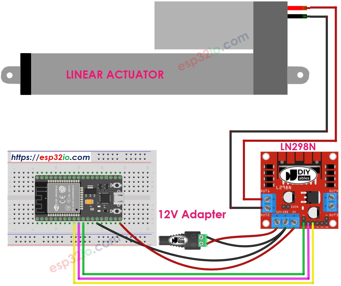
This image is created using Fritzing. Click to enlarge image
How To Make Linear Actuator Expand/Retract
The moving direction of a Linear Actuator can be controlled by applying a logic HIGH/LOW to IN1 and IN2 pins. The below table illustrates how to control the direction in both channels.
| IN1 pin | IN2 pin | Direction |
|---|---|---|
| LOW | LOW | Linear Actuator A stops |
| HIGH | HIGH | Linear Actuator A stops |
| HIGH | LOW | Linear Actuator A extends |
| LOW | HIGH | Linear Actuator A retracts |
- Extends Linear Actuator A
- Retracts Linear Actuator A
※ NOTE THAT:
The moving direction is inverted if the OUT1 & OUT2 pin connects to two pins of the linear actuator in an inverse way. If so, it just needs to swap between OUT1 & OUT2 pin or change the control signal on IN1 and IN2 pin in the code.
How To Stop Linear Actuator from Extending or Retracting
The linear actuator automatically stops extending/retracting when it reaches the limit. We can also programmably stop it from extending/retracting while it has not reached the limit.
There are two ways to stop linear actuator
- Controls the speed to 0
- Controls IN1 IN2 pins to the same value (LOW or HIGH)
- Or
How To Control the Speed of Linear Actuator via L298N Driver
It is simple to control the speed of the linear actuator. Instead of controlling ENA pin to HIGH, We generate a PWM signal to the ENA pin. We can do this by:
- Connect an ESP32 pin to ENA of L298N
- Generate PWM signal to ENA pin by using analogWrite() function. L298N Driver amplify PWM signal to linear actuator
The speed is a value between 0 and 255. If the speed is 0, the linear actuator stops. If the speed is 255, the linear actuator extends/retracts at maximum speed.
If you're unfamiliar with how to supply power to the ESP32 and other components, you can find guidance in the following tutorial: The best way to Power ESP32 and sensors/displays.
ESP32 Example Code
The below code does:
- Extend actuator at maximum speed
- Stop the linear actuator
- Retract actuator at maximum speed
- Stop the linear actuator
Quick Instructions
- Remove all three jumpers on the L298N module.
- Copy the above code and paste it to Arduino IDE
- Compile and upload code to ESP32 board by clicking Upload button on Arduino IDE
- You will see:
- Linear actuator extends and then stops when reaching the limit
- Linear actuator keeps the position a mount of time
- Linear actuator retracts and then stops when reaching the limit
- Linear actuator keeps the position a mount of time
- The above process is run repeatedly.
Video Tutorial
Making video is a time-consuming work. If the video tutorial is necessary for your learning, please let us know by subscribing to our YouTube channel , If the demand for video is high, we will make the video tutorial.