ESP32 - Door Sensor
The door sensor (also known as entry sensor, contact sensor, or window sensor) is widely used in many kinds of application, especially for security. It is used to detect/monitor entrances (such as door, window ...). This tutorial instructs you how to use ESP32 with the door sensor.
This tutorial shows how to program the ESP32 using the Arduino language (C/C++) via the Arduino IDE. If you’d like to learn how to program the ESP32 with MicroPython, visit this ESP32 MicroPython - Door Sensor tutorial.
Hardware Used In This Tutorial
Or you can buy the following kits:
| 1 | × | DIYables ESP32 Starter Kit (ESP32 included) | |
| 1 | × | DIYables Sensor Kit (18 sensors/displays) |
Introduction to Door Sensor
Door Sensor Pinout
The door sensor has two components:
- One magnet
- One reed switch, which has two wires
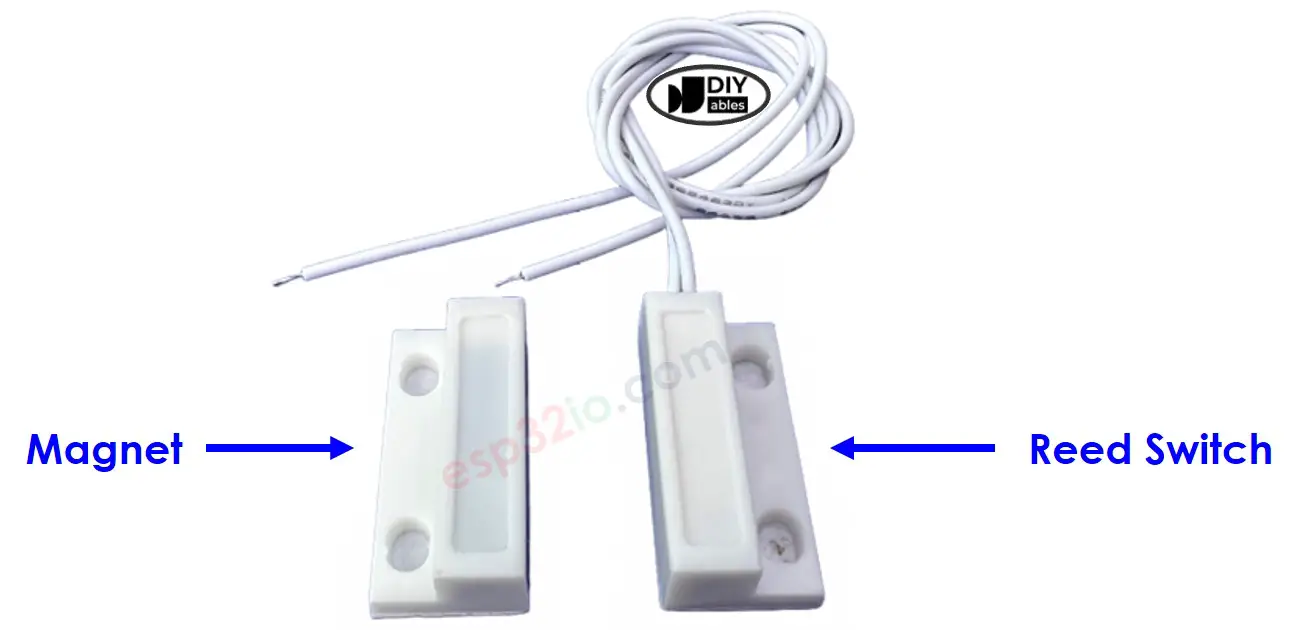
Just like the switch/button, we do NOT need to differentiate the two wires of the reed switch.
How Door Sensor Works
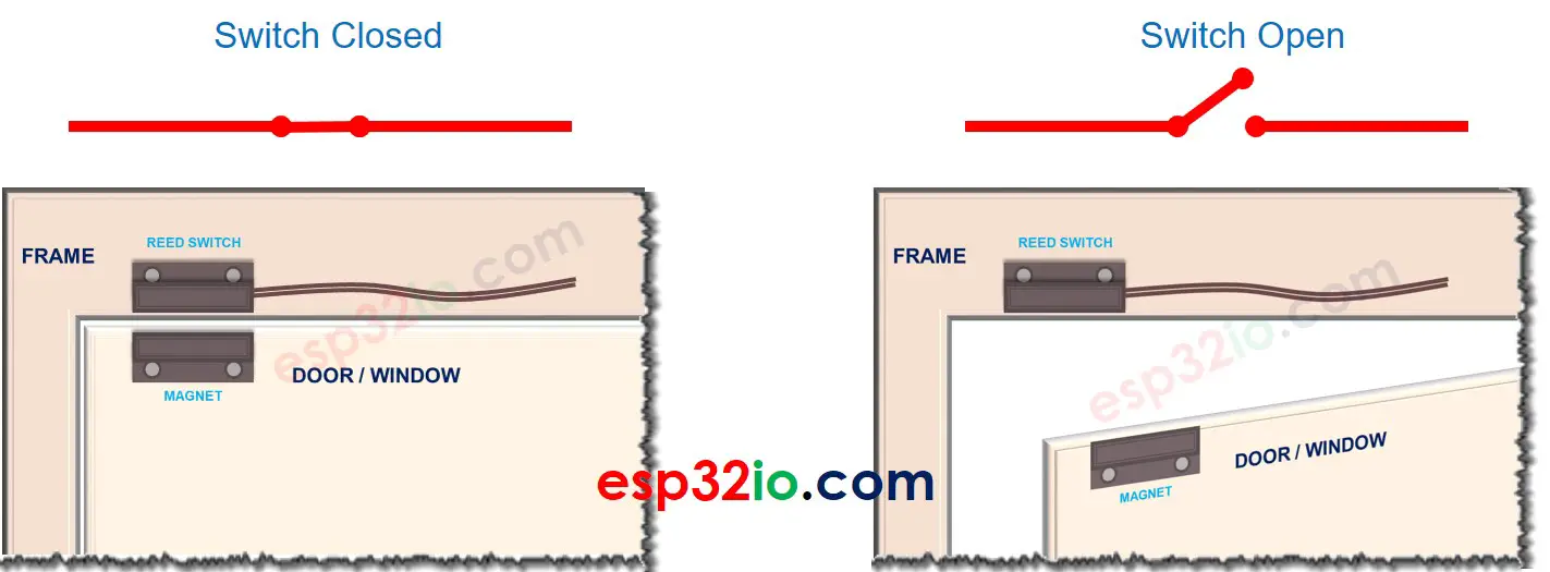
The magnet and the reed switch are installed on the door/windows as follows:
- The magnet is the movable part. It should be attached to the door/window
- The reed switch is the fixed part. It should be attached to the door frame
The two components are in contact when the door is closed.
- The reed switch circuit is closed when it is near to the magnet
- The reed switch circuit is open when it is far from the magnet
※ NOTE THAT:
Just like a button, we MUST use the pull-up or pull-down resistor on the ESP32 pin, which connects to the reed switch
If we connect reed switch as follows: one wire to GND, the other to ESP32's input pin with a pull-up resistor:
- The ESP32's input pin is LOW when the magnet is near to the reed switch
- The ESP32's input pin is HIGH when the magnet is far from the reed switch
So:
- If the ESP32's input pin is LOW, the door is closed
- If the ESP32's input pin is HIGH, the door is opened
- If the ESP32's input pin changes from LOW to HIGH, the door is opening
- If the ESP32's input pin changes from HIGH to LOW, the door is closing
Wiring Diagram between Door Sensor and ESP32
- How to connect ESP32 and door sensor using breadboard
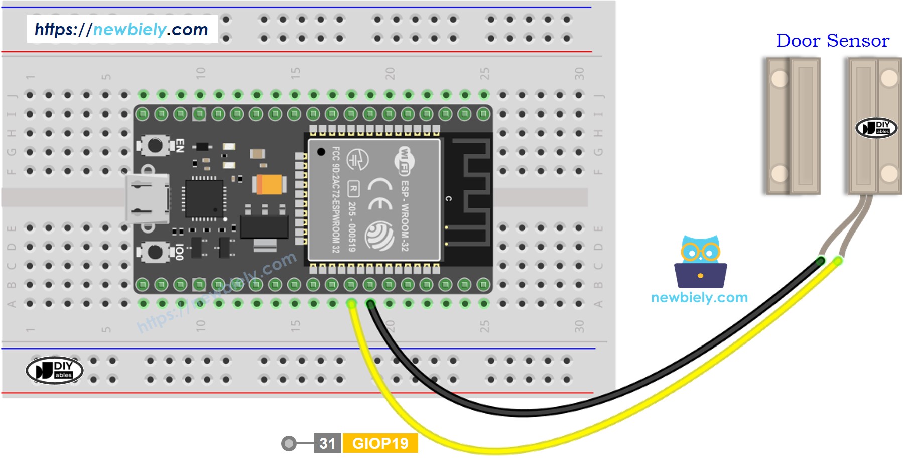
This image is created using Fritzing. Click to enlarge image
- How to connect ESP32 and door sensor using screw terminal block breakout board
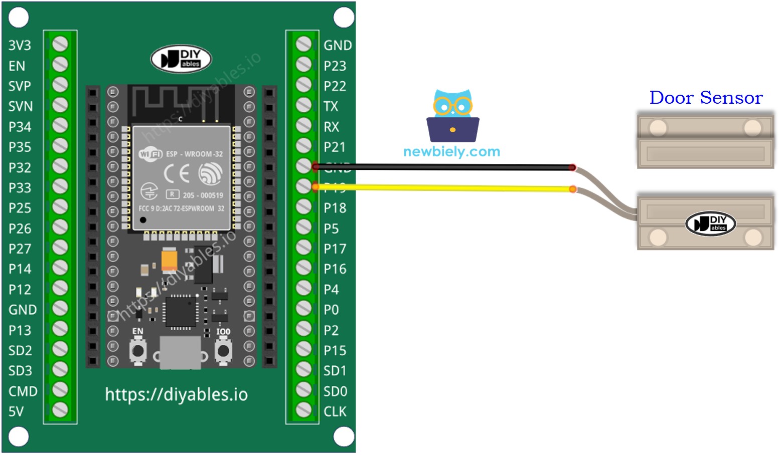
If you're unfamiliar with how to supply power to the ESP32 and other components, you can find guidance in the following tutorial: The best way to Power ESP32 and sensors/displays.
How To Program Door Sensor
- Initializes the ESP32 pin to the digital input mode by using pinMode() function. For example, pin GPIO19
- Reads the state of the ESP32 pin by using digitalRead() function.
ESP32 Code - Check Door Open and Close State
Quick Instructions
- If this is the first time you use ESP32, see how to setup environment for ESP32 on Arduino IDE.
- Copy the above code and paste it to Arduino IDE.
- Compile and upload code to ESP32 board by clicking Upload button on Arduino IDE
- Move the magnet close to the reed switch and them move it far from the reed switch.
- See the result on Serial Monitor. It looks like the below:.
ESP32 Code - Detect Door-opening and Door-closing Events
- Copy the above code and paste it to Arduino IDE.
- Compile and upload code to ESP32 board by clicking Upload button on Arduino IDE
- Move the magnet close to the reed switch and them move it far from the reed switch.
- See the result on Serial Monitor. It looks like the below:.
Video Tutorial
Making video is a time-consuming work. If the video tutorial is necessary for your learning, please let us know by subscribing to our YouTube channel , If the demand for video is high, we will make the video tutorial.