ESP32 - Button
The button is a basic component and widely used in many ESP32 projects. It is not simple as it looks like (because of mechanical, physical characteristics). Beginners may have a lot of troubles with it. This tutorial makes it easy for the beginners. Let's start!
※ NOTE THAT:
Before presenting about the button, We would like to notice that there are two common mistakes that newbies usually meet:
- The floating input problem:
- Symptom: When connecting a button to ESP32 input pin, the state of the input pin is random and not matched with the button's pressing state.
- Cause: The button pin is NOT used a pull-down resistor or a pull-up resistor.
- Solution: ⇒ Use a pull-down resistor or a pull-up resistor on the input pin. The detail will be described later in this tutorial.
- Symptom: The code on ESP32 reads the state of the button and identifies the pressing event by detecting the state change (HIGH to LOW, or LOW to HIGH). When the button is actually pressed only one time, ESP32 code detects multiple presses rather than once.
- Cause: Due to mechanical and physical characteristics, when you do a single press on a button, the state of the input pin is quickly toggled between LOW and HIGH several times rather than once
- Solution: ⇒ Debounce. The detail will be described in ESP32 - Button - Debounce tutorial.
The chattering phenomenon causes the malfunction in only some kinds of application that needs to detect exactly number of the pressing. In some kind of application, it is harmless.
This tutorial shows how to program the ESP32 using the Arduino language (C/C++) via the Arduino IDE. If you’d like to learn how to program the ESP32 with MicroPython, visit this ESP32 MicroPython - Button tutorial.
Hardware Used In This Tutorial
Or you can buy the following kits:
| 1 | × | DIYables ESP32 Starter Kit (ESP32 included) | |
| 1 | × | DIYables Sensor Kit (18 sensors/displays) |
Introduction to Button
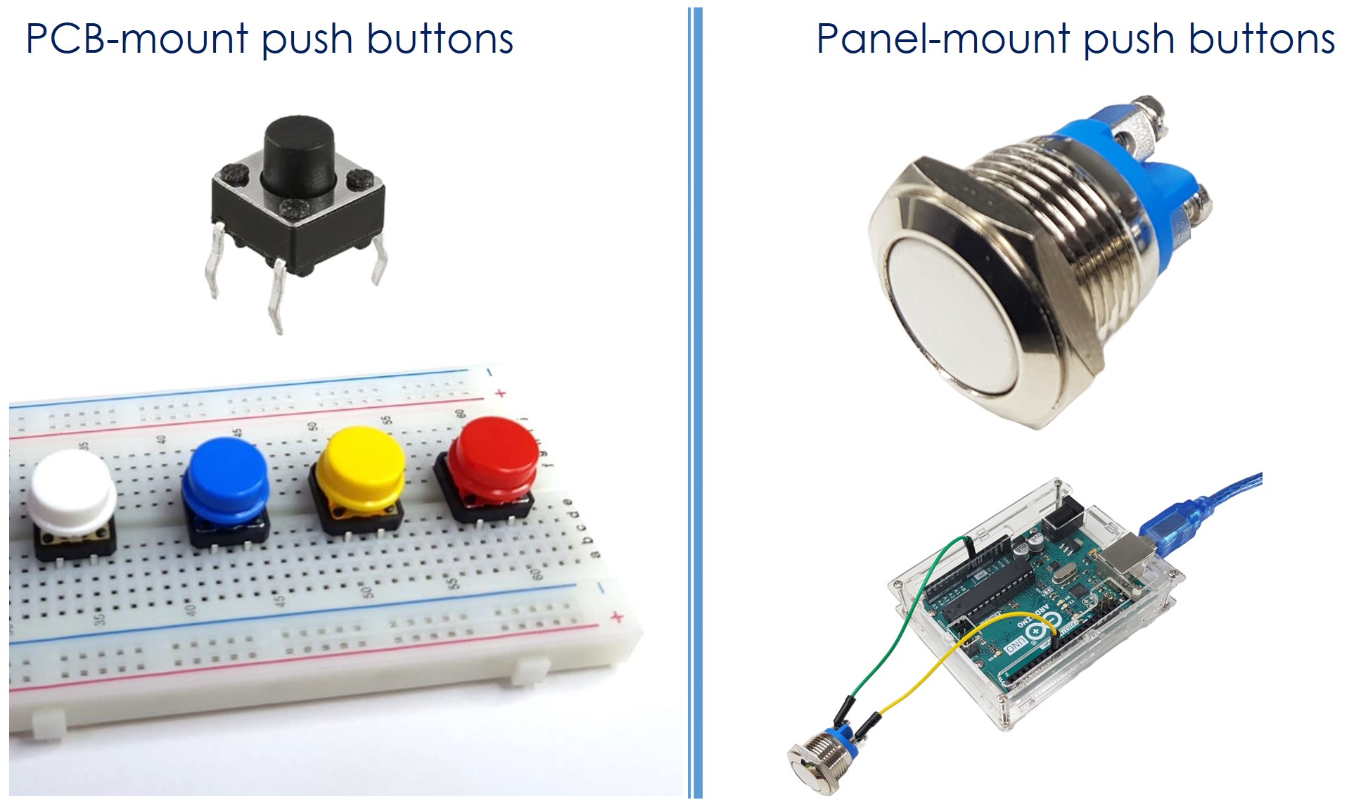
The push button, also referred to as a pushbutton, tactile button, or momentary switch, is a type of switch that closes when pressed and held, and opens when released. Various types of push buttons exist, broadly categorized into two groups:
- PCB-mount push buttons (suitable for breadboard mounting)
- Panel-mount push buttons
Button Pinout
A PCB-mount button usually has four pins that are internally connected in pairs.

We only need to use two of the four pins, which are NOT in the same connected pair. Accordingly, There are four ways to do wiring with the button (see bimage below)
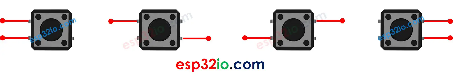
Actually, because of symmetry, these four ways becomes two ways. The rest of this tutorial will use two pins: Pin A and Pin B that are not connected together.
⇒ The button receives the force from users. To make it stand stably and firmly in PCB (board), It has four pins to resist the pressing force.
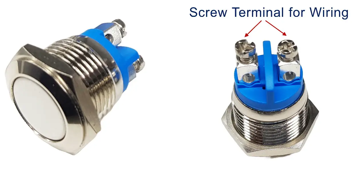
A panel-mount button usually has two pins.
The push button module includes an built-in pull-down resistor, which ensures that the output remains LOW when the button is not pressed. It has three pins:
- GND: Connect this pin to ground.
- VCC: Connect this pin to a 3.3V power supply.
- OUT: Connect this pin to a digital input on your ESP32.
With this configuration, the module outputs LOW when the button is not pressed and outputs HIGH when the button is pressed.
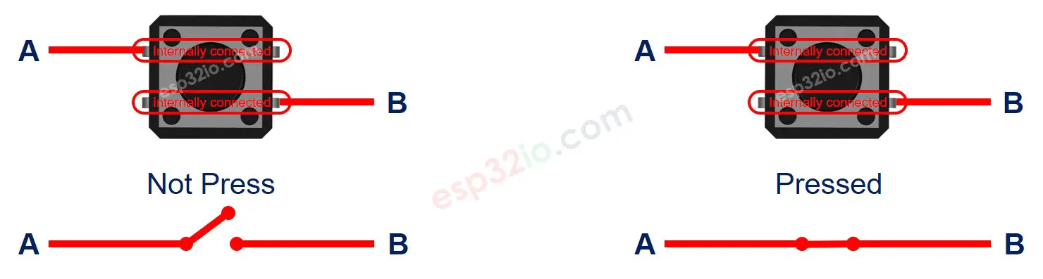
How Button Works
- When the button is pressed, the pin A is connected to the pin B
- When the button is NOT pressed, the pin A is NOT connected to the pin B
ESP32 - Button
One button's pin is connected to a digital input pin of ESP32. The other pin is connected to VCC or GND. In ESP32 code, by reading the state of the input pin, we can infer the button is pressed or NOT.
Input State and Pressing State
The relation between the state of the input pin and the button's pressing state depends on how we connect the button with ESP32 and the setting of the ESP32's pin. There are two ways to use a button with ESP32:
- One button's pin is connected to a digital input pin of ESP32, the other pin is connected to VCC:
- A pull-down resistor MUST be used
- If the button is pressed, the state of ESP32's pin is HIGH. Otherwise, the state of ESP32's pin is LOW
- A pull-up resistor MUST be used
- If the button is pressed, the state of ESP32's pin is LOW. Otherwise, the state of ESP32's pin is HIGH
※ NOTE THAT:
If neither a pull-down resistor nor a pull-up resistor is used, the state of the input pin is random between HIGH or LOW (unstable, unfixed) when the button is NOT pressed. This is called The “floating input problem”. This results in the malfunction.
To make it simple for newbies, this tutorial highly recommens newbies using an internal pull-up resistor for ESP32 pin. No external resistor is required. This saves the hardware, simplifies the wiring diagram.
Wiring Diagram between Button and ESP32
- Wiring Diagram between ESP32 and PCB-mount button
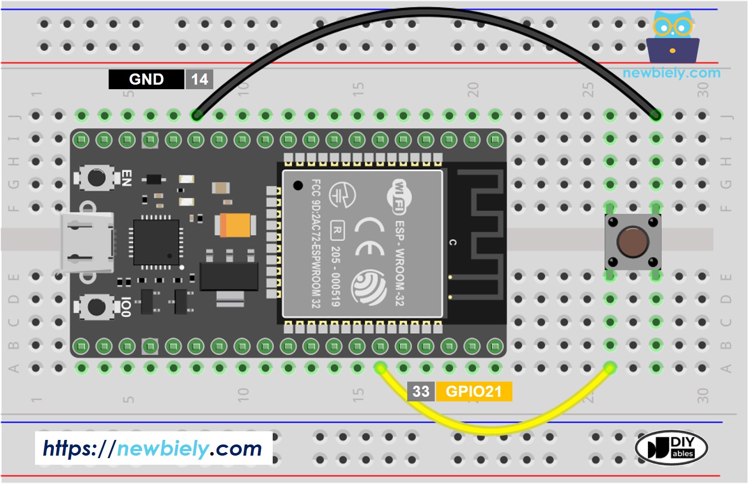
This image is created using Fritzing. Click to enlarge image
- Wiring Diagram between ESP32 and panel-mount button
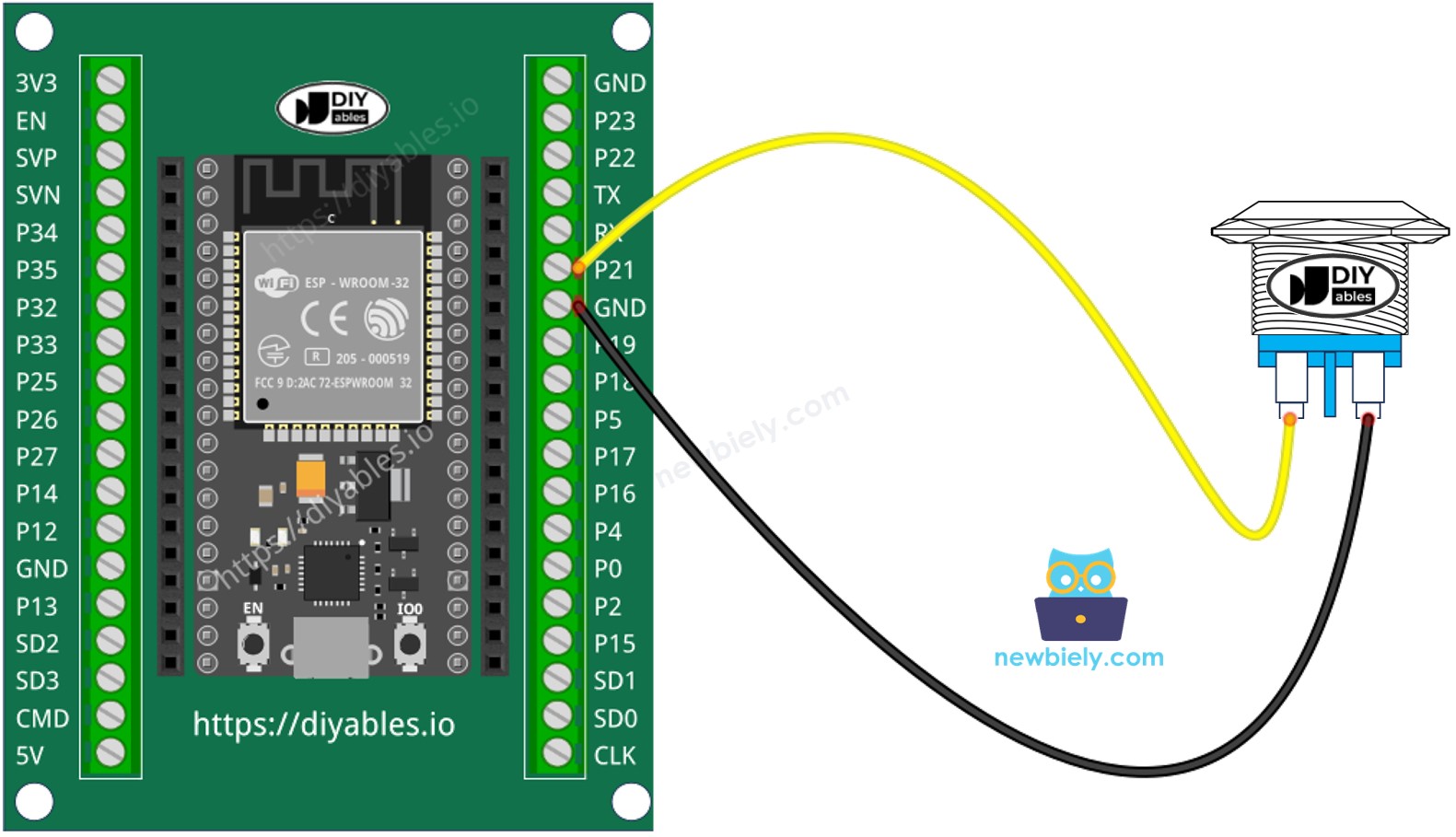
This image is created using Fritzing. Click to enlarge image
If you're unfamiliar with how to supply power to the ESP32 and other components, you can find guidance in the following tutorial: The best way to Power ESP32 and sensors/displays.
ESP32 Code
Quick Instructions
- If this is the first time you use ESP32, see how to setup environment for ESP32 on Arduino IDE.
- Do the wiring as above image.
- Connect the ESP32 board to your PC via a micro USB cable
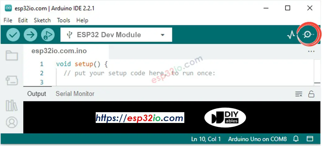
- Open Arduino IDE on your PC.
- Select the right ESP32 board (e.g. ESP32 Dev Module) and COM port.
- Copy the below code and paste it to Arduino IDE.
- Compile and upload code to ESP32 board by clicking Upload button on Arduino IDE

- Open Serial Monitor on Arduino IDE
- Press and release the button several time
- See the result on Serial Monitor. It looks like the below::
1 is HIGH, 0 is LOW.
Line-by-line Code Explanation
The above ESP32 code contains line-by-line explanation. Please read the comments in the code!
Modifying ESP32 Code
Let's modify the code to detect the press and release events
Quick Instructions
- If this is the first time you use ESP32, see how to setup environment for ESP32 on Arduino IDE.
- Modify the code as below
- Compile and upload code to ESP32 board by clicking Upload button on Arduino IDE
- Open Serial Monitor on Arduino IDE
- Press the button and then release
- See the result on Serial Monitor. It looks like the below:
※ NOTE THAT:
- The Serial Monitor may print several pressed and released events even though you did only one press and release. This is a normal behavior of the button. This behavior is called the “chattering phenomenon”. In some application, we need a method to eliminate it. You can learn more in ESP32 - Button Debounce tutorial.
- To make it simple for beginners, especially when using multiple buttons, we created a library, called ezButton. You can learn about ezButton library here.
- For the button module, use pinMode(BUTTON_PIN, INPUT). It outputs LOW when unpressed and HIGH when pressed.
Video Tutorial
Making video is a time-consuming work. If the video tutorial is necessary for your learning, please let us know by subscribing to our YouTube channel , If the demand for video is high, we will make the video tutorial.
Additional Knowledge
- SHOULD: If the sensor has two states: closed and open, it need a pull-up or pull-down resistor to make these states become two states: LOW and HIGH. For example, push-button, switch, magnetic contact switch (door sensor)...
- SHOULD NOT: If the sensor outputs two voltage levels (LOW and HIGH), it does NOT need a pull-up or pull-down resistor. For example, motion sensor, touch sensor ...