ESP32 - DS1307 RTC Module
In this guide, we are going to learn how to use the DS1307 RTC module with ESP32. In detail, we will learn the following topics:
- How to connect the DS1307 RTC module to ESP32.
- How to program ESP32 to read date and time from the DS1307 RTC module (seconds, minutes, hours, day, date, month, and year)
Hardware Used In This Tutorial
Or you can buy the following kits:
| 1 | × | DIYables ESP32 Starter Kit (ESP32 included) | |
| 1 | × | DIYables Sensor Kit (18 sensors/displays) |
Introduction to Real-Time Clock DS1307 Module
ESP32 itself has some time-related functions such as millis(), micros(). However, they can not provide the date and time (seconds, minutes, hours, day, date, month, and year). To get date and time, we needs to use a Real-Time Clock (RTC) module such as DS3231, DS1370. DS3231 Module has higher precision than DS1370. See DS3231 vs DS1307
Pinout
Real-Time Clock DS1307 Module includes 12 pins. However, for normal use, it needs to use 4 pins: VCC, GND, SDA, SCL:
- SCL pin: is a clock pin for I2C interface.
- SDA pin: is a data pin for I2C interface.
- VCC pin: supplies power for the module. It can be anywhere between 3.3V to 5.5V.
- GND pin: is a ground pin.
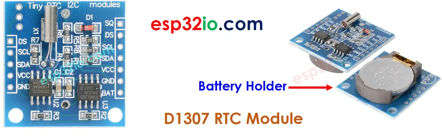
The DS1307 Module also has a battery holder.
- If we insert a CR2032 battery, It keeps the time on module running when the main power is off.
- If we do not insert the battery, the time information is lost if the main power is off and you need to set the time again.
Wiring Diagram
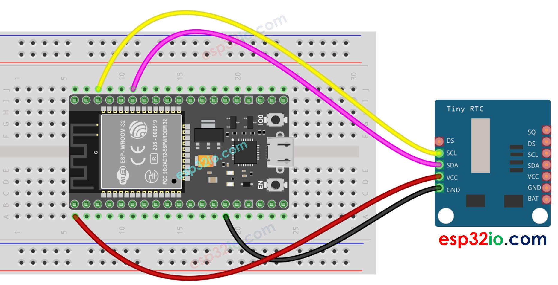
This image is created using Fritzing. Click to enlarge image
ESP32 - DS1307 RTC Module
| DS1307 RTC Module | ESP32 |
|---|---|
| Vin | 3.3V |
| GND | GND |
| SDA | GPIO21 |
| SCL | GPIO22 |
If you're unfamiliar with how to supply power to the ESP32 and other components, you can find guidance in the following tutorial: The best way to Power ESP32 and sensors/displays.
How To Program For DS1307 RTC Module
- Include the library:
- Declare a RTC object:
- Initialize RTC:
- For the first time, set the RTC to the date & time on PC the sketch was compiled
- Reads date and time information from RTC module
ESP32 Code – How to get data and time
Quick Instructions
- If this is the first time you use ESP32, see how to setup environment for ESP32 on Arduino IDE.
- Do the wiring as above image.
- Connect the ESP32 board to your PC via a micro USB cable
- Open Arduino IDE on your PC.
- Select the right ESP32 board (e.g. ESP32 Dev Module) and COM port.
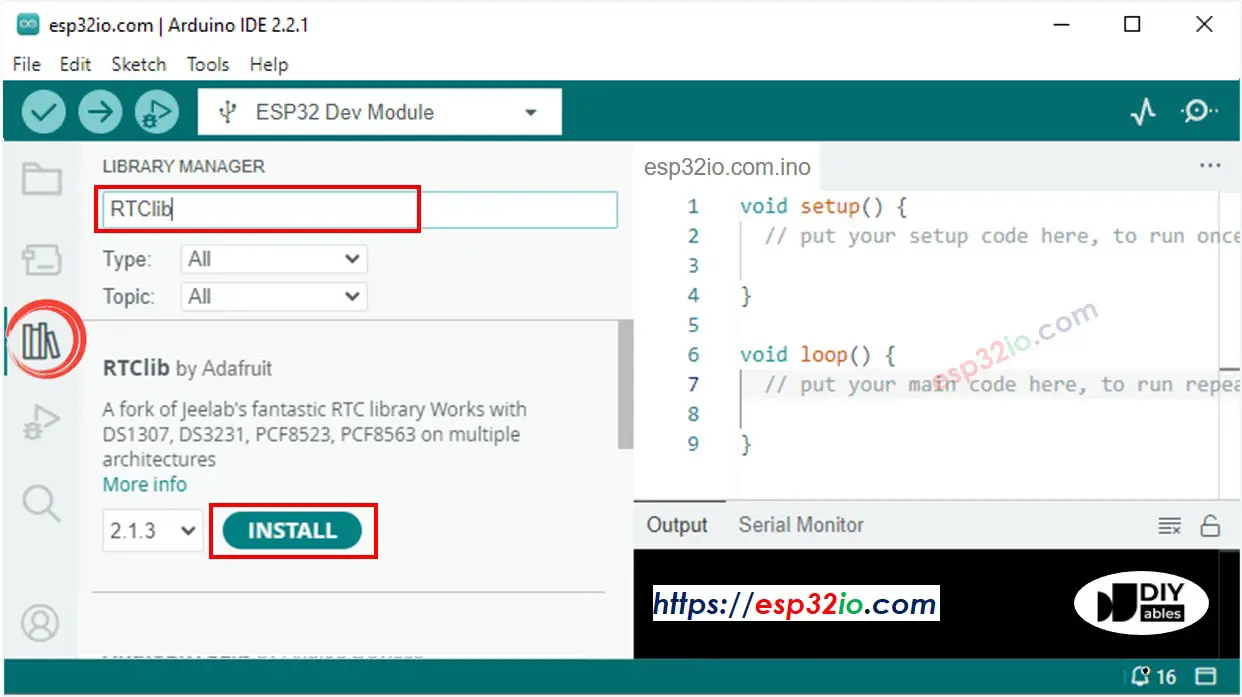
- Open the Library Manager by clicking on the Library Manager icon on the left navigation bar of Arduino IDE
- Search “RTClib”, then find the RTC library by Adafruit
- Click Install button to install RTC library.
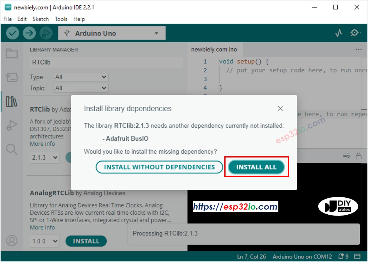
- You may be asked to install dependencies for the library
- Install all dependencies for the library by clicking on Install All button.
- Copy the above code and paste it to Arduino IDE
- Compile and upload code to ESP32 board by clicking Upload button on Arduino IDE
- Open Serial Monitor on Arduino IDE
- See the output on Serial Monitor.
Video Tutorial
Making video is a time-consuming work. If the video tutorial is necessary for your learning, please let us know by subscribing to our YouTube channel , If the demand for video is high, we will make the video tutorial.