ESP32 - Water Sensor
This tutorial instructs you how to use ESP32 and water sensor to detect rainfall, water leakage, tank overflow, and measure the water level.
This tutorial shows how to program the ESP32 using the Arduino language (C/C++) via the Arduino IDE. If you’d like to learn how to program the ESP32 with MicroPython, visit this ESP32 MicroPython - Water Sensor tutorial.
Hardware Used In This Tutorial
Or you can buy the following kits:
| 1 | × | DIYables ESP32 Starter Kit (ESP32 included) | |
| 1 | × | DIYables Sensor Kit (18 sensors/displays) |
Introduction to Water Level Sensor
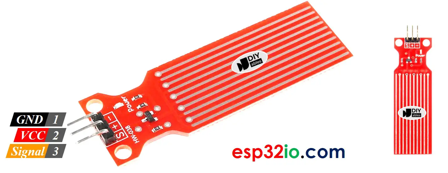
Water Level Sensor Pinout
The water level sensor includes 3 pins:
- S (Signal) pin: This pin outputs analog voltage that is in proportion to the water level. This pin should be connected to an analog input pin of ESP32.
- + (VCC) pin: connects this pin to 3.3V or 5V.
- - (GND) pin: connects this pin to GND.
How Water Level Sensor Works
Simply, the more water the sensor is sank in, the higher the output voltage in the S pin is. By measuring the voltage, we can know the water level.
Wiring Diagram
In theory, we can provide power to the water sensor by connecting the sensor's VCC and GND pins to ESP32's 3.3V and GND pins, respectively.
However, that way is not recommended in practice. If we supply power to the water sensor constantly, the water sensor is electrochemically corroded faster by the moist environment ⇒ It is better to provide power to the water sensor only and only when reading the value from the sensor. To do so, We can connect the sensor's VCC pin to an ESP32's digital pin, and program the ESP32's pin to HIGH before reading and LOW after reading.
- How to connect ESP32 and water sensor using breadboard
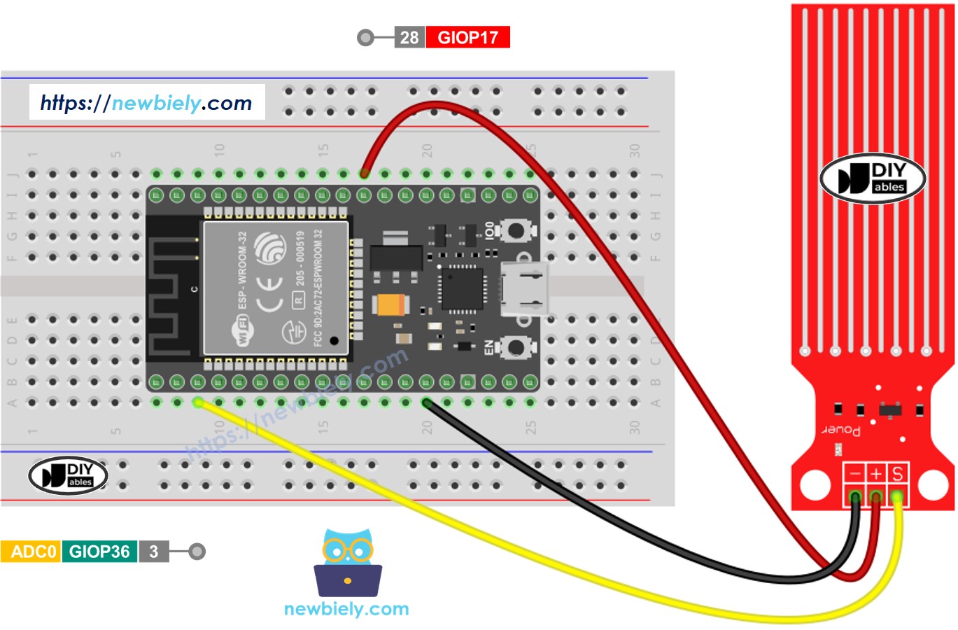
This image is created using Fritzing. Click to enlarge image
- How to connect ESP32 and water sensor using screw terminal block breakout board (powered via USB cable)
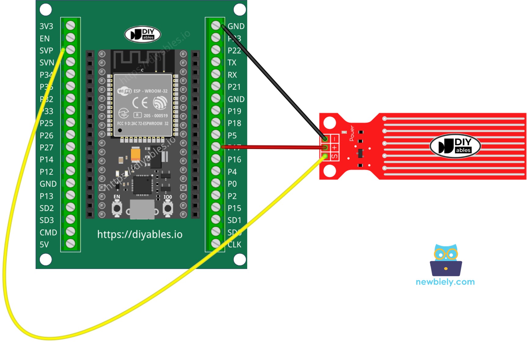
If you're unfamiliar with how to supply power to the ESP32 and other components, you can find guidance in the following tutorial: The best way to Power ESP32 and sensors/displays.
ESP32 Code - Reading Value from Water Sensor
Quick Instructions
- If this is the first time you use ESP32, see how to setup environment for ESP32 on Arduino IDE.
- Copy the above code and paste it to Arduino IDE.
- Compile and upload code to ESP32 board by clicking Upload button on Arduino IDE
- Slowly dip the sensor into the water ( a glass of water).
- See the result on Serial Monitor. It looks like the below:. The value 0 when the sensor is not touching anything.
※ NOTE THAT:
The water sensor is not designed to be completely sank, only the exposed traces on the PCB can embed into the water. Please be careful to install it.
How To Detect Water Leakage
To detect the water leakage, rainfall, and tank overflow, we just need to compare the sensor's value with a threshold. The threshold is determined in the calibration part of this tutorial.
Let's make ESP32 turns on an LED if the water leakage is detected.
Wiring Diagram
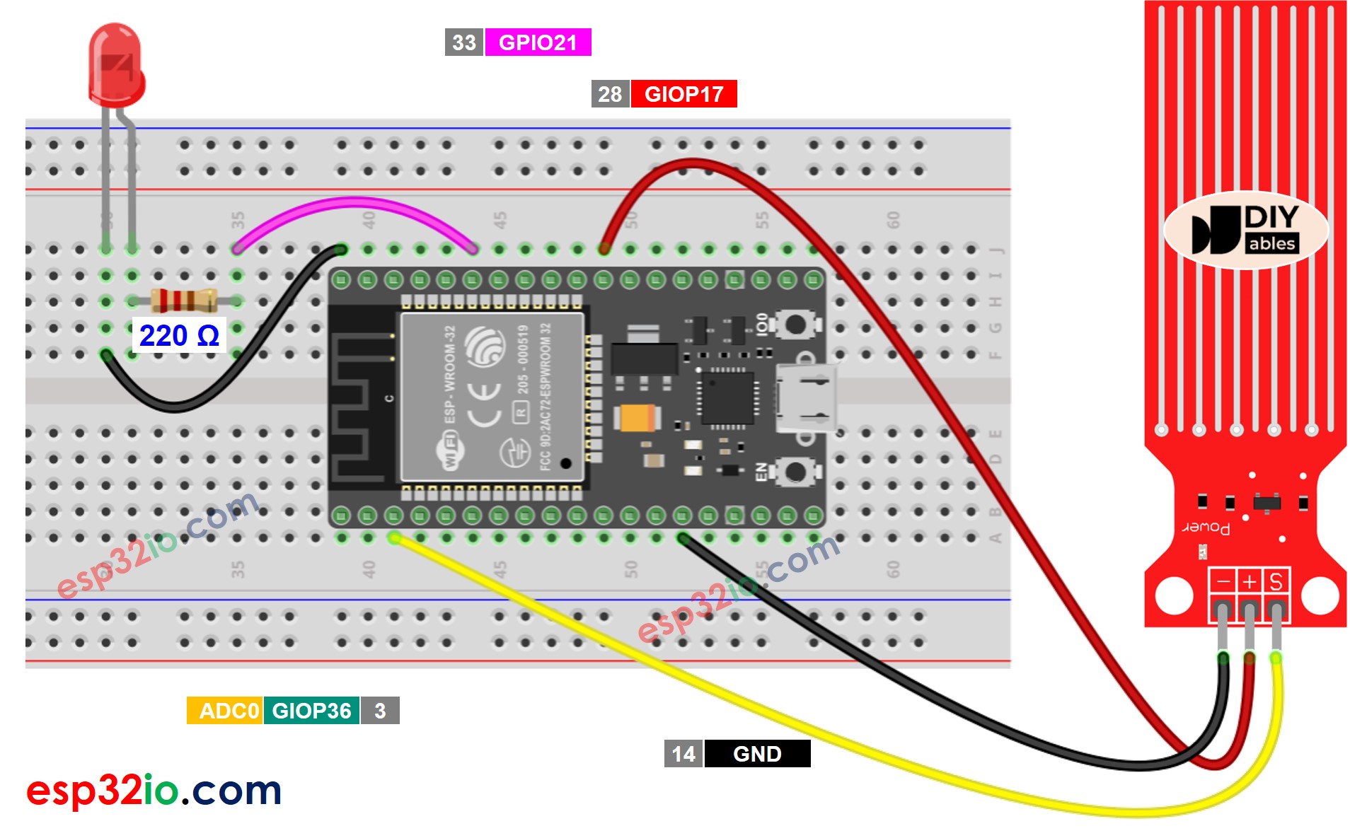
This image is created using Fritzing. Click to enlarge image
ESP32 Code - Detecting Water Leakage
How To Measure The Water Level
The below code divides the water level into 4 levels.
※ NOTE THAT:
- SENSOR_MIN and SENSOR_MAX is determined by the calibration process.
- The above mapping method is not accurate. However, it is acceptable in many applications.
Water Level Sensor Calibration
See how to calibrate the water lever sensor
※ NOTE THAT:
This tutorial uses the analogRead() function to read values from an ADC (Analog-to-Digital Converter) connected to a water sensor. The ESP32 ADC is good for projects that do NOT need high accuracy. However, for projects that need precise measurements, please note:
- The ESP32 ADC is not perfectly accurate and might need calibration for correct results. Each ESP32 board can be a bit different, so you need to calibrate the ADC for each individual board.
- Calibration can be difficult, especially for beginners, and might not always give the exact results you want.
For projects that need high precision, consider using an external ADC (e.g ADS1115) with the ESP32 or using an Arduino, which has a more reliable ADC. If you still want to calibrate the ESP32 ADC, refer to ESP32 ADC Calibration Driver
Video Tutorial
Making video is a time-consuming work. If the video tutorial is necessary for your learning, please let us know by subscribing to our YouTube channel , If the demand for video is high, we will make the video tutorial.