ESP32 - GPIO Interrupt
In this tutorial, We are going to learn how to use the GPIO interrupts in ESP32. GPIO interrupts on the ESP32 enable responsive and efficient handling of external events, making them essential for real-time applications in IoT and embedded systems. By understanding and properly configuring these interrupts, you can create robust and responsive projects that react immediately to the environment.
Hardware Used In This Tutorial
Or you can buy the following kits:
| 1 | × | DIYables ESP32 Starter Kit (ESP32 included) | |
| 1 | × | DIYables Sensor Kit (18 sensors/displays) |
What is a GPIO Interrupt?
A GPIO interrupt is a signal that causes the processor to stop its current execution and jump to a specific piece of code known as an interrupt service routine (ISR). This allows the ESP32 to handle high-priority tasks immediately, without the need for continuous polling of the GPIO pins.
Interrupts In ESP32
The ESP32 supports various types of GPIO interrupts:
- Rising Edge: Triggered when the GPIO pin transitions from LOW to HIGH.
- Falling Edge: Triggered when the GPIO pin transitions from HIGH to LOW.
- Both Edge: Triggered on any change of state, either from LOW to HIGH or HIGH to LOW.
- Level Low: Triggered when the GPIO pin stays LOW.
- Level High: Triggered when the GPIO pin stays HIGH.
How to configure GPIO Interrupts on ESP32
To configure a GPIO interrupt on the ESP32, you need to follow these steps:
Initialize the GPIO: Set the GPIO pin mode to input or output as required. For example:
Attach the Interrupt: Use the attachInterrupt() function to link the GPIO pin to an ISR.
This function accepts three arguments:
- GPIO_Pin: Specifies the GPIO pin to be used as the interrupt pin, indicating which pin the ESP32 should monitor.
- ISR_function: The name of the function that will be called whenever the interrupt occurs.
- mode: Defines the condition that triggers the interrupt. There are five predefined constants that can be used:
- RISING: Trigger when the pin transitions from LOW to HIGH (on Rising Edge).
- FALLING: Trigger when the pin transitions from HIGH to LOW (on Falling Edge).
- CHANGE: Trigger on any change in the pin's state (on Both Edge).
- HIGH: Trigger when the pin is HIGH (on Level High).
- LOW: Trigger when the pin is LOW (on Level Low).
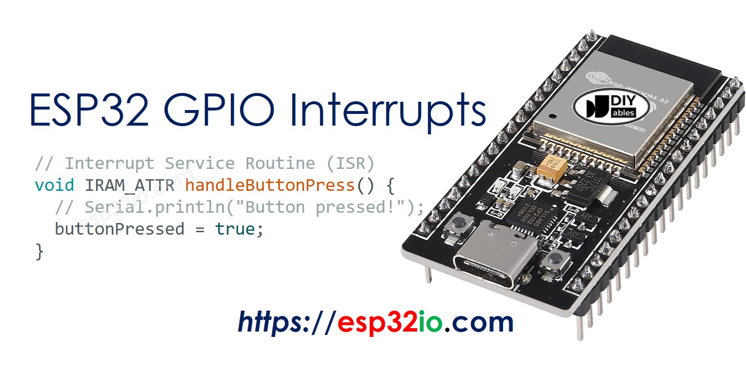
Define the ISR function: Write the interrupt service routine that will execute when the interrupt is triggered.
The Interrupt Service Routine (ISR) is a function that is invoked every time an interrupt occurs on the GPIO pin. Its syntax looks like below.
Let's dive into a practical example of using interrupts with an ESP32's GPIO pin connected to a button.
Wiring Diagram
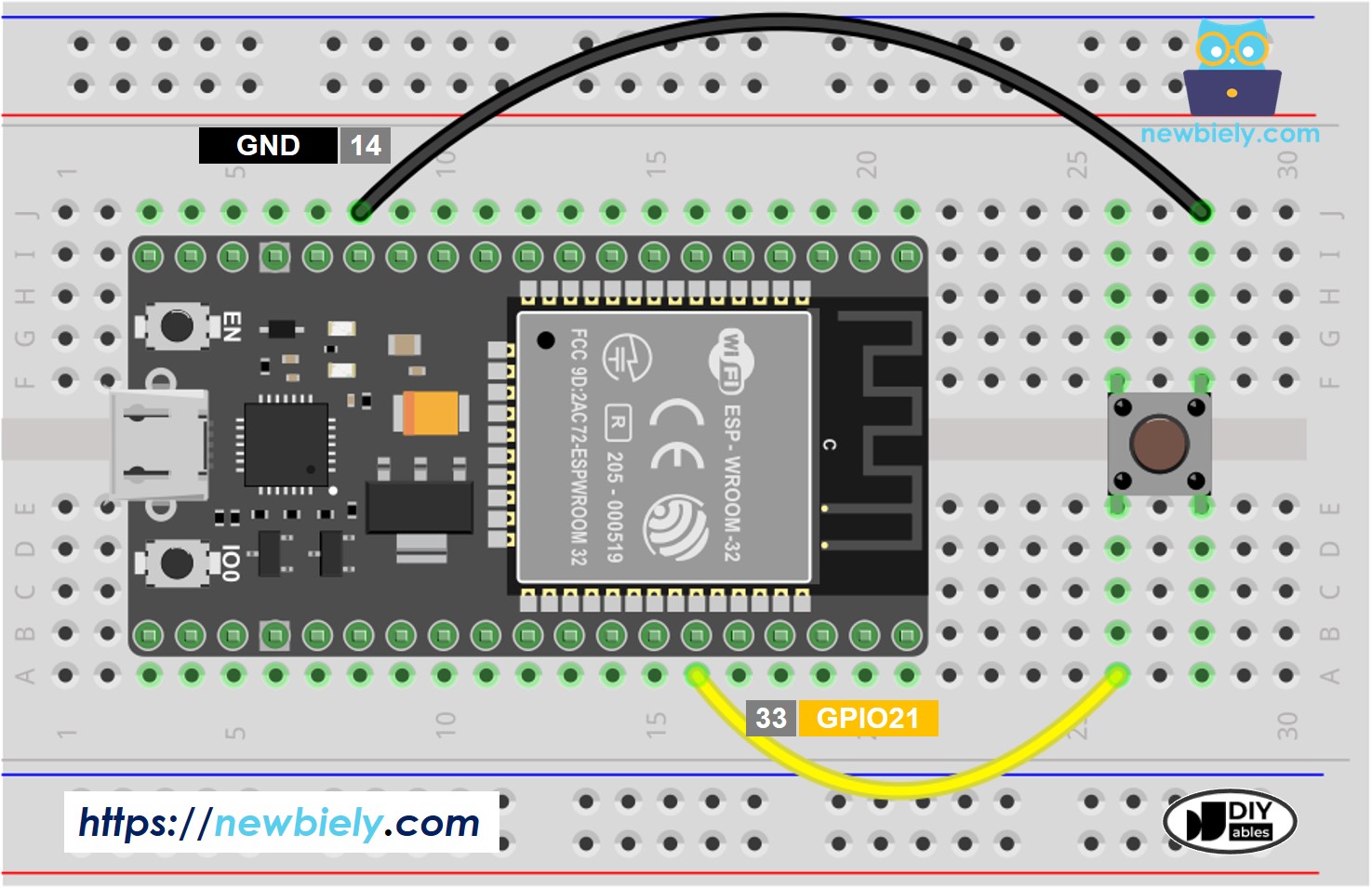
This image is created using Fritzing. Click to enlarge image
If you're unfamiliar with how to supply power to the ESP32 and other components, you can find guidance in the following tutorial: The best way to Power ESP32 and sensors/displays.
ESP32 Interrupts Code
In this example:
- The BUTTON_PIN is defined as GPIO21.
- The pinMode() function sets the GPIO pin as an input with an internal pull-up resistor.
- The attachInterrupt() function attaches the ISR handleButtonPress to the BUTTON_PIN, configured to trigger on a falling edge.
- The handleButtonPress function is the ISR that executes when the button is pressed.
The above code demonstrates what interrupt code looks like, but it may not work in practice because it uses the Serial.println() function, which takes longer to process than is allowed in an interrupt service routine.
To test how interrupts work, see the practical code example below:
Quick Instructions
- If this is the first time you use ESP32, see how to setup environment for ESP32 on Arduino IDE.
- Do the wiring as above image.
- Connect the ESP32 board to your PC via a micro USB cable
- Open Arduino IDE on your PC.
- Select the right ESP32 board (e.g. ESP32 Dev Module) and COM port.
- Copy the above code and open with Arduino IDE
- Click Upload button on Arduino IDE to upload code to ESP32
- Press button several times
- Check out the result on Serial Monitor
You may notice that a single button press results in multiple pressing events being shown on the Serial Monitor. This is not an interrupt problem but an issue with the button itself. To learn how to solve this, refer to the ESP32 - Button - Debounce tutorial.
You can see another example that uses interrupts in this ESP32 - Rotary Encoder tutorial.
Important Considerations
- No Parameters or Return Values: An ISR function cannot have any parameters and should not return anything.
- ISR Execution Time: Keep the ISR code as short and efficient as possible. Long ISRs can cause the system to miss other interrupts or degrade overall performance.
- Concurrency: Be mindful of shared resources accessed within ISRs. Use atomic operations or disable interrupts if necessary to avoid race conditions. Specifically, use the volatile keyword for variables accessed both inside and outside the ISR function.
- IRAM_ATTR: Place the ISR code in IRAM using the IRAM_ATTR attribute to ensure it runs quickly without fetching from flash memory.
Video Tutorial
Making video is a time-consuming work. If the video tutorial is necessary for your learning, please let us know by subscribing to our YouTube channel , If the demand for video is high, we will make the video tutorial.