ESP32 - Control Pump
This tutorial instructs you how to use ESP32 to control a pump. You can extend this tutorial to build the DIY aquarium, cocktail machine, coffee machine, or irrigation system...
This tutorial shows how to program the ESP32 using the Arduino language (C/C++) via the Arduino IDE. If you’d like to learn how to program the ESP32 with MicroPython, visit this ESP32 MicroPython - Controls Pump tutorial.
Hardware Used In This Tutorial
Or you can buy the following kits:
| 1 | × | DIYables ESP32 Starter Kit (ESP32 included) | |
| 1 | × | DIYables Sensor Kit (18 sensors/displays) |
Introduction to 12V Pump
Pump Pinout
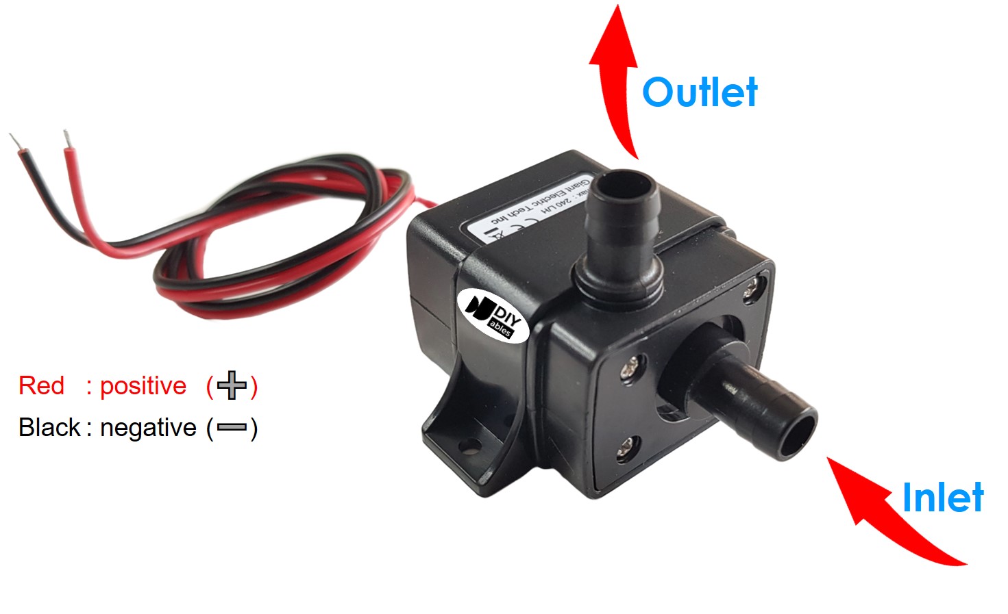
A 12V Pump has two wires:
- Negative (-) wire (black): connect this wire to the negative wire of 12V DC power supply
- Positive (+) wire (red): connect this wire to the Positive wire of 12V DC power supply
How to Control Pump using ESP32
If we connect a 12V power supply to a pump, the pump will work. We can programmatically control a pump by using ESP32. To do so, we need a relay in between the pump ESP32 board. We have a specific tutorial about relay, which contains detailed information and step-by-step instructions about hardware pinout, working principle, wiring connection to ESP32, ESP32 code... Learn about relay in the ESP32 - Relay tutorial
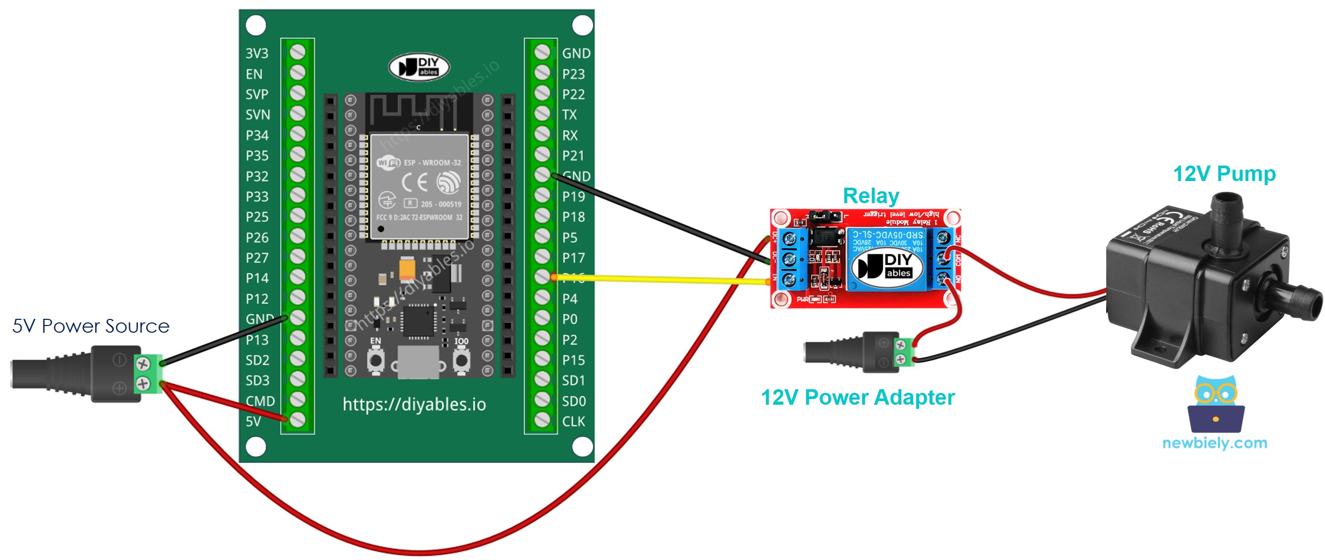
Wiring Diagram between ESP32, Relay and Pump
- How to connect ESP32 and controls pump using breadboard (powered via USB cable)
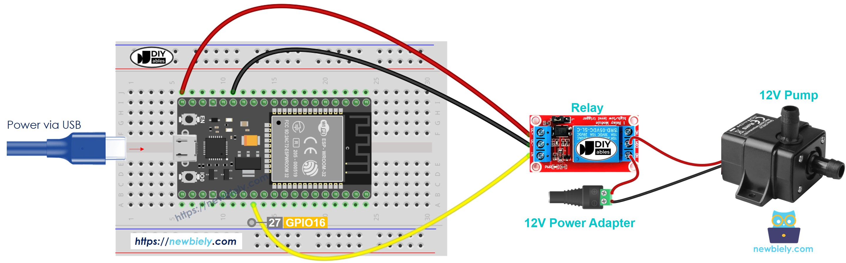
This image is created using Fritzing. Click to enlarge image
- How to connect ESP32 and controls pump using breadboard (powered via Vin pin)
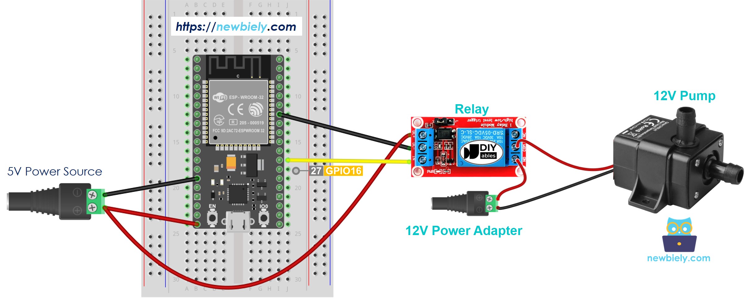
This image is created using Fritzing. Click to enlarge image
- How to connect ESP32 and controls pump using screw terminal block breakout board (powered via USB cable)
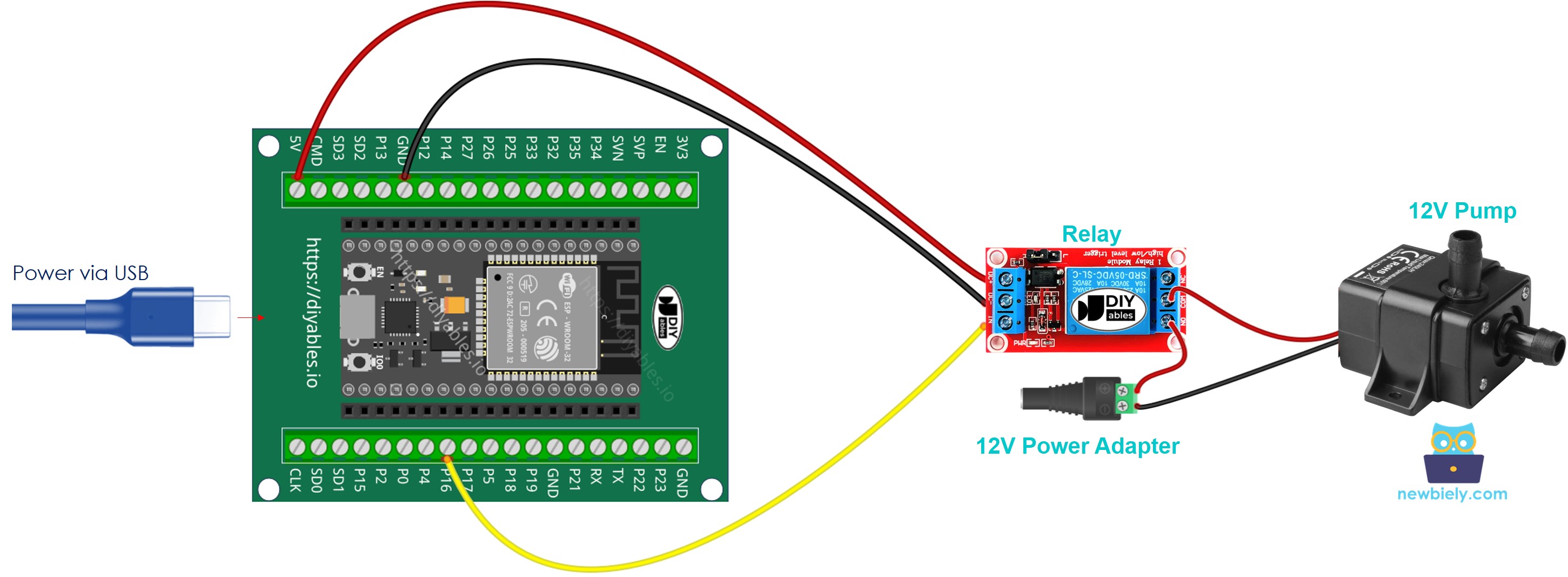
- How to connect ESP32 and controls pump using screw terminal block breakout board (powered via Vin pin)
If you're unfamiliar with how to supply power to the ESP32 and other components, you can find guidance in the following tutorial: The best way to Power ESP32 and sensors/displays.
ESP32 - Pump Code
The below code periodically turns the pump ON/OFF in every 4 seconds.
Quick Instructions
- If this is the first time you use ESP32, see how to setup environment for ESP32 on Arduino IDE.
- Do the wiring as above image.
- Connect the ESP32 board to your PC via a micro USB cable
- Open Arduino IDE on your PC.
- Select the right ESP32 board (e.g. ESP32 Dev Module) and COM port.
- Copy the above code and paste it to Arduino IDE.
- Compile and upload code to ESP32 board by clicking Upload button on Arduino IDE
- See the pump's state
Line-by-line Code Explanation
The above ESP32 code contains line-by-line explanation. Please read the comments in the code!
Video Tutorial
Making video is a time-consuming work. If the video tutorial is necessary for your learning, please let us know by subscribing to our YouTube channel , If the demand for video is high, we will make the video tutorial.