ESP32 - LED - Blink
This tutorial instructs you how to use esp32 to blink an LED. This is one of the first tutorials that beginers learn.
This tutorial shows how to program the ESP32 using the Arduino language (C/C++) via the Arduino IDE. If you’d like to learn how to program the ESP32 with MicroPython, visit this ESP32 MicroPython - LED - Blink tutorial.
Hardware Used In This Tutorial
Or you can buy the following kits:
| 1 | × | DIYables ESP32 Starter Kit (ESP32 included) | |
| 1 | × | DIYables Sensor Kit (18 sensors/displays) |
Buy Note: Want to make wiring easier? Try the LED Module. It already has a built-in resistor, so no extra parts needed!
Introduction to LED
LED Pinout
LED includes two pins:
- Cathode(-) pin: connect this pin to GND (0V)
- Anode(+) pin: is used to control LED's state

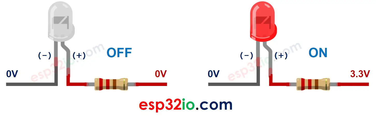
How LED Works
After connecting the cathode(-) to GND:
- If we connect VCC to the anode(+), LED is ON.
- If we connect GND to the anode(+), LED is OFF.
In addition, if a PWM signal is generated to the anode(+), the LED's brightness is changed in proportion to the PWM duty cycle. See more detailed in ESP32 fade LED tutorial.
※ NOTE THAT:
- Usually, A resistor is required to protect LED from burning. The resistor can be placed between the anode(+) and VCC or between the cathode(-) and GND. The resistance value depends on the LED's specification.
- Some LEDs have a built-in resistor, so there is no need to use a resistor for them.
ESP32 - LED
The ESP32's digital output pin's voltage can be programmed to VCC or GND. By connecting the digital output pin to LED, we can programmatically control the LED's state.
Wiring Diagram between LED and ESP32
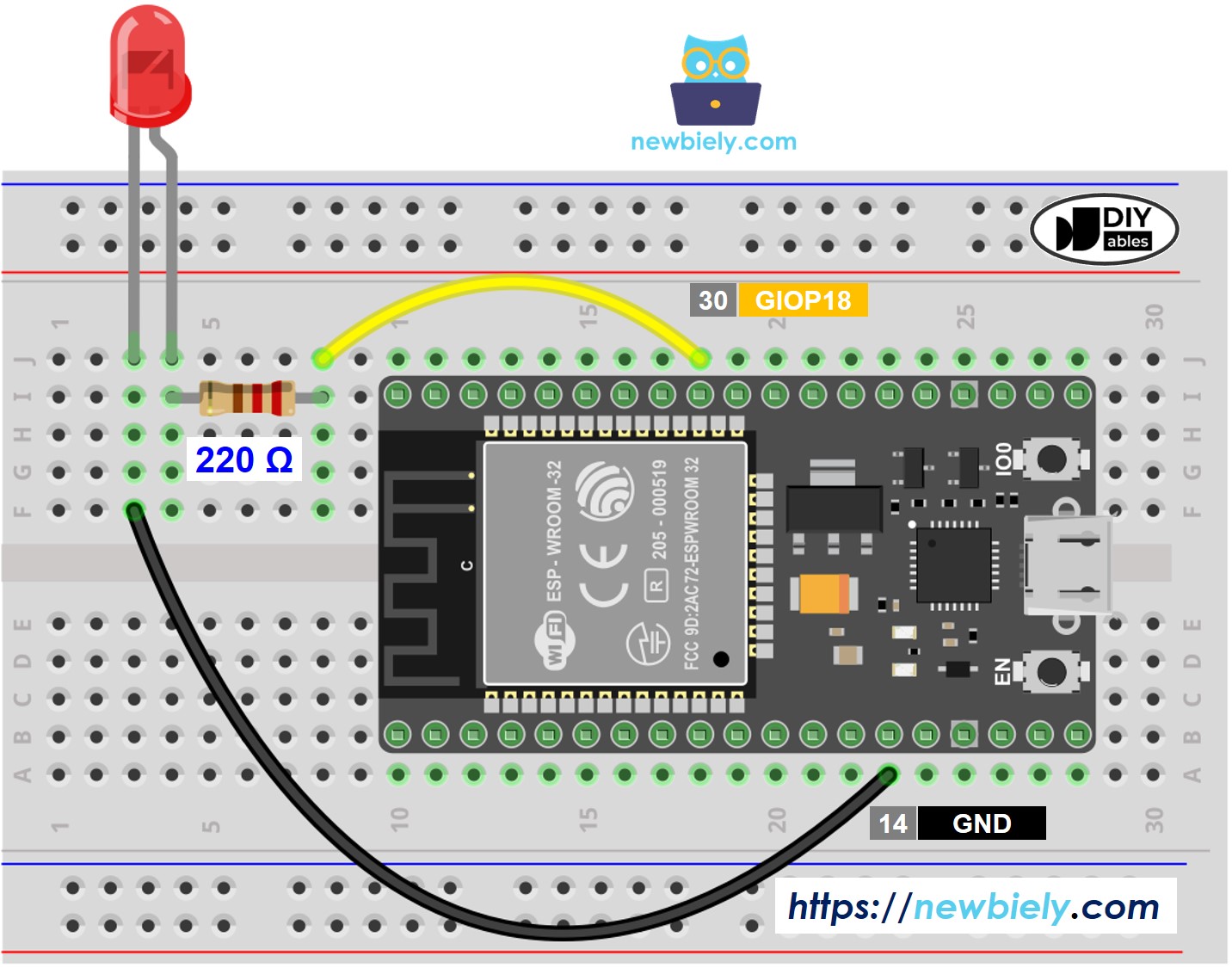
This image is created using Fritzing. Click to enlarge image
If you're unfamiliar with how to supply power to the ESP32 and other components, you can find guidance in the following tutorial: The best way to Power ESP32 and sensors/displays.
How To Program
- Configure an ESP32's pin to the digital output mode by using pinMode() function. For example, pin GPIO18:
ESP32 Code
Quick Instructions
- If this is the first time you use ESP32, see how to setup environment for ESP32 on Arduino IDE.
- Do the wiring as above image.
- Connect the ESP32 board to your PC via a micro USB cable
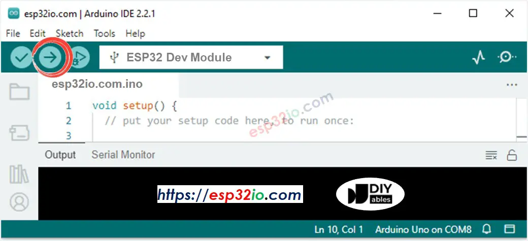
- Open Arduino IDE on your PC.
- Select the right ESP32 board (e.g. ESP32 Dev Module) and COM port.
- Copy the below code and paste it to Arduino IDE.
- Compile and upload code to ESP32 board by clicking Upload button on Arduino IDE
- See the result: The LED blinks one time per second.
Line-by-line Code Explanation
The above ESP32 code contains line-by-line explanation. Please read the comments in the code!
※ NOTE THAT:
The above code uses the delay(). This function blocks ESP32 from doing other tasks . To avoid blocking ESP32, see ESP32 blink without delay
Video Tutorial
Making video is a time-consuming work. If the video tutorial is necessary for your learning, please let us know by subscribing to our YouTube channel , If the demand for video is high, we will make the video tutorial.