ESP32 - RFID/NFC
This tutorial instructs you how to use ESP32 withRC522 RFID/NFC reader to read the information from RFID/NFC tag.
Hardware Used In This Tutorial
Or you can buy the following kits:
| 1 | × | DIYables ESP32 Starter Kit (ESP32 included) | |
| 1 | × | DIYables Sensor Kit (18 sensors/displays) |
Introduction to RFID-RC522 Module
Pinout
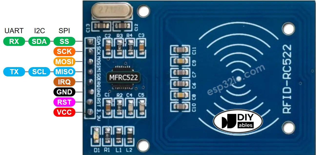
The RFID-RC522 module has 8 pins, some pins are shared among three communication interfaces: SPI, I2C, UART. At a time, only one communication mode can be used. The pin are:
- GND pin: connect this pin to GND (0V)
- VCC pin: connect this pin to VCC (3.3)
- RST pin: is a pin for reset and power-down. When this pin goes low, hard power-down is enabled. On the rising edge, the module is reset.
- IRQ pin: is an interrupt pin that can alert the ESP32 when RFID tag comes into its detection range.
- MISO/SCL/TX pin: works as:
- MISO pin if SPI interface is enabled
- SCL pin if I2C interface is enabled
- TX pin if UART interface is enabled.
- MOSI pin: works as MOSI if SPI interface is enabled.
- SCK pin: works as SCK if SPI interface is enabled
- SS/SDA/RX pin: works as:
- SS pin if SPI interface is enabled
- SDA pin when I2C interface is enabled
- RX pin when UART interface is enabled.
- The pins order can vary according to manufacturers. ALWAYS use the labels printed on the module. The above image shows the pinout of the modules from DIYables manufacturer.
- The RFID-RC522 module works with 3.3V. Do not connect the RFID-RC522 module's VCC pin to 5V. 5V can burn the RFID-RC522 module.
- This tutorial uses SPI interface for communication between ESP32 and RFID-RC522 module.
※ NOTE THAT:
Wiring Diagram
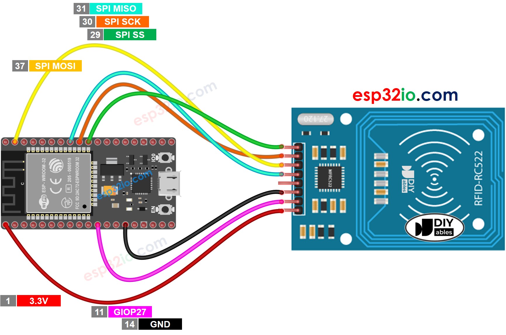
This image is created using Fritzing. Click to enlarge image
The wiring table between RFID/NFC RC522 Module and ESP32
| RFID/NFC RC522 Module | ESP32 |
|---|---|
| SS pin | → (29) GPIO5 |
| SCK pin | → (30) GPIO18 |
| MOSI pin | → (37) GPIO23 |
| MISO pin | → (31) GPIO19 |
| IRQ pin(not connected) | |
| GND pin | → GND |
| RST pin | → (11) GPIO27 |
| VCC pin | → 3.3V |
If you're unfamiliar with how to supply power to the ESP32 and other components, you can find guidance in the following tutorial: The best way to Power ESP32 and sensors/displays.
ESP32 RFID/NFC Code
Quick Instructions
- If this is the first time you use ESP32, see how to setup environment for ESP32 on Arduino IDE.
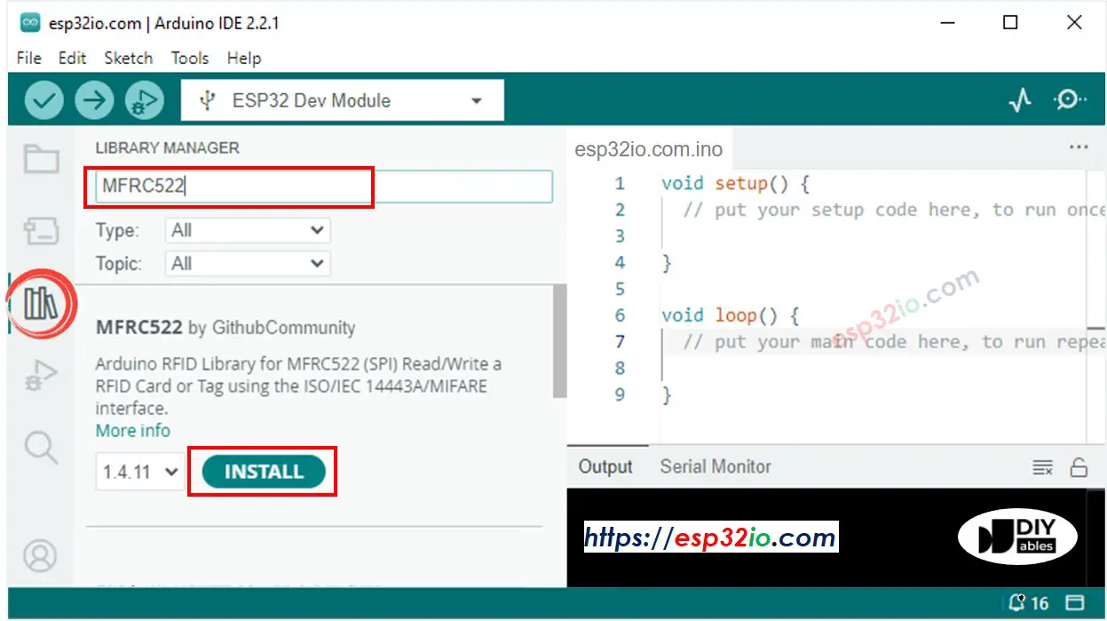
- Click to the Libraries icon on the left bar of the Arduino IDE.
- Type “MFRC522” on the search box, then look for the library by GithubCommunity
- Install the library by clicking on Install button.
- Copy the above code and paste it to Arduino IDE.
- Compile and upload code to ESP32 board by clicking Upload button on Arduino IDE
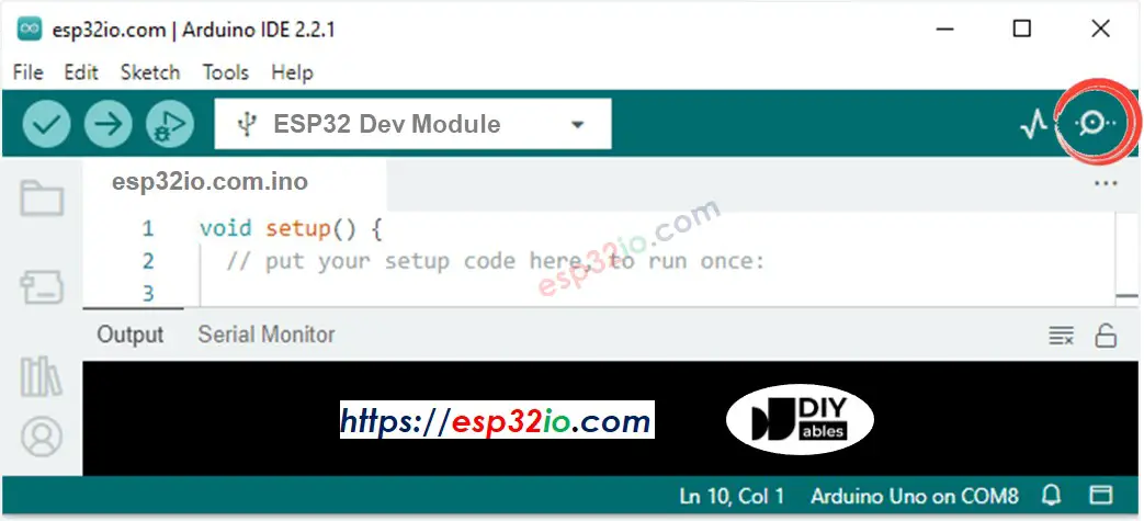
- Open Serial Monitor on Arduino IDE
- Tap several RFID/NFC tags on RFID-RC522 module
- See the UID printed on Serial Monitor
Video Tutorial
Making video is a time-consuming work. If the video tutorial is necessary for your learning, please let us know by subscribing to our YouTube channel , If the demand for video is high, we will make the video tutorial.