ESP32 - Rotary Encoder
In this guide, you'll learn how to use the rotary encoder with an ESP32. Here's what we'll learn:
- What are differences between a rotary encoder and a potentiometer
- How the rotary encoder works
- How to connect the rotary encoder to the ESP32
- How to write code for the ESP32 to read the direction and position from the rotary encoder WITHOUT interrupt.
- How to write code for the ESP32 to read the direction and position from the rotary encoder WITH interrupt.
Hardware Used In This Tutorial
Or you can buy the following kits:
| 1 | × | DIYables ESP32 Starter Kit (ESP32 included) | |
| 1 | × | DIYables Sensor Kit (18 sensors/displays) |
Introduction to Rotary Encoder
A spinning knob, like on a radio, can send signals that turn into electricity. It helps us know how much it turned and where it's put. There are two main types:
- Incremental encoder: This one uses quick signals to measure how much something changed its position.
- Absolute encoder: This type gives a secret code for each spot, which helps us find where something is, even if the power goes away.
This lesson is mainly about the first type, the incremental encoder.
Rotary Encoder Module Pinout
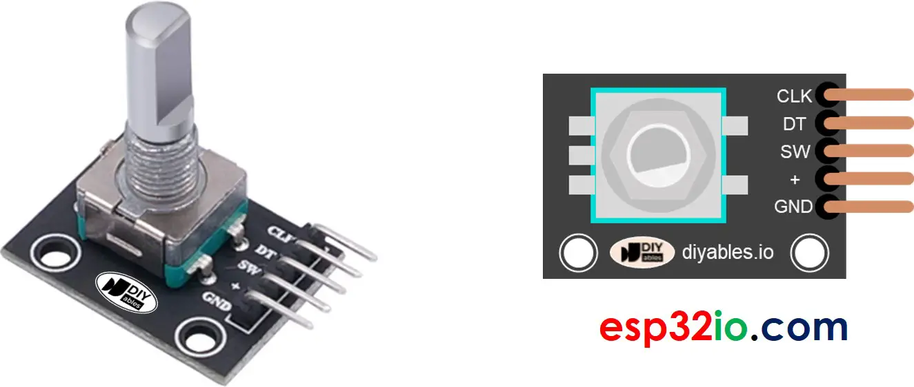
A rotary encoder module has 4 pins:
- CLK pin (Output A): is the main pulse that tells us how much rotation has occurred. Whenever you turn the knob by one detent (click) in either direction, the CLK pin outputs a signal that is a completes a full cycle (LOW → HIGH → LOW).
- DT pin (Output B): acts like the CLK pin but outputs a signal lags behind CLK signal by 90 degrees. It helps us figure out the direction of rotation (clockwise or anticlockwise).
- SW pin: comes from the encoder's button. It’s normally open. When we add a pull-up resistor to this pin, the SW pin will be HIGH when the knob isn't pushed and LOW when it's pushed.
- VCC pin (+): needs to be connected to VCC (between 3.3 and 5 volts)
- GND pin: needs to be connected to GND (0V)
Rotary Encoder vs Potentiometer
You may confuse the rotary encoder with the potentiometer. but they are distinct components. Here's a comparison between them:
- Rotary encoder is like the modern version of potentiometer, but they can do more things.
- Rotary encoder can spin around in a full circle without stopping, while potentiometer can only turn about three-quarters of the circle.
- Rotary encoder outputs pulses, while potentiometer outputs the analog voltage.
- Rotary encoder is handy when you just need to figure out how much the knob has moved, not exactly where it is. Potentiometer is useful when you really need to know exactly where a knob is.
How Rotary Encoder Works
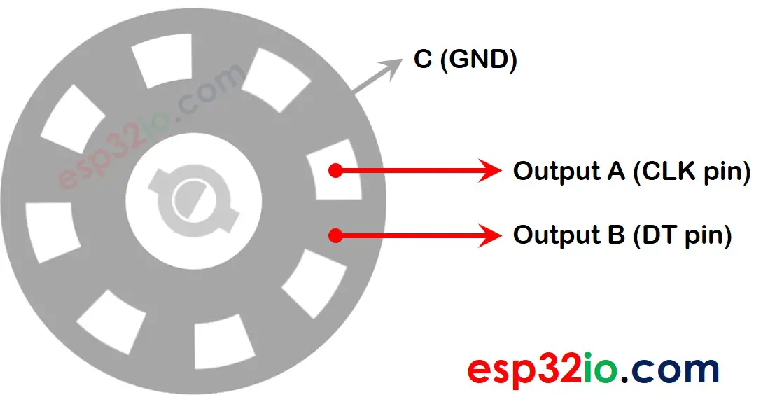
Inside the encoder, there's a little disc with slots that's connected to a pin called C, which acts like a shared ground. You've got two more pins, A and B.
- When you turn the knob, pins A and B touch that shared ground pin C, but the order in which they touch it depends on which way you're turning the knob (either clockwise or counterclockwise).
- These touches create two signals. They're a bit different in timing because one pin touches the ground before the other. Those signals are out of sync by 90 degrees, which is called quadrature encoding.
- If you turn the knob clockwise, pin A touches the ground before pin B does. But if you go counterclockwise, pin B hits the ground first before pin A.
- By checking when each pin touches or leaves the ground, we can figure out which way the knob is turning. We do this by checking what happens to pin B when pin A changes.
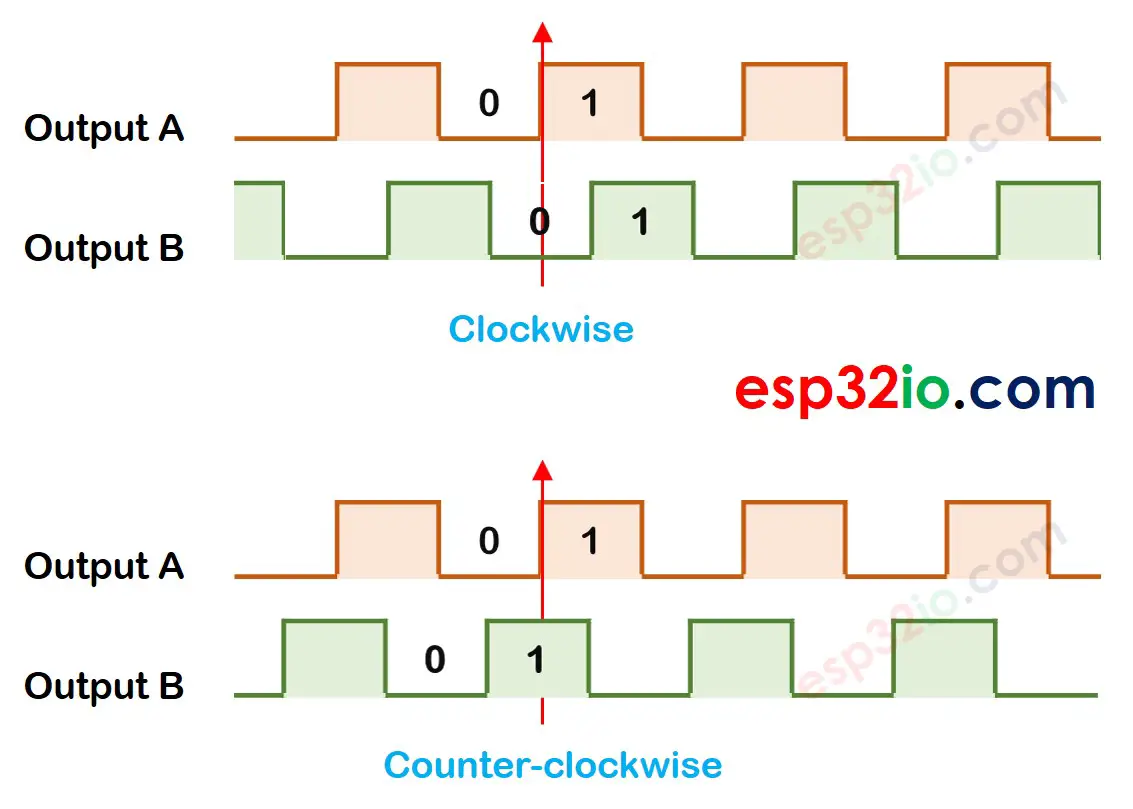
When A changes states from LOW to HIGH:
- If B is HIGH, the knob is turned counter-clockwise.
- If B is LOW, the knob is turned clockwise.
※ NOTE THAT:
Pin A and B are connected to CLK and DT pins. However, depending on the manufacturers, the order may be different. The codes provided below are tested with the rotary encoder from DIYables
How To Program For Rotary Encoder
- ESP32 reads the signal from CLK pin
- If the state changes from LOW to HIGH, then ESP32 reads the state of the DT pin.
- If the DT pin is HIGH, the knob is turned in the counter-clockwise direction, ESP32 increases the counter by 1
- If the DT pin is LOW, the knob is turned in the clockwise direction, ESP32 decreases the counter by 1
Wiring Diagram
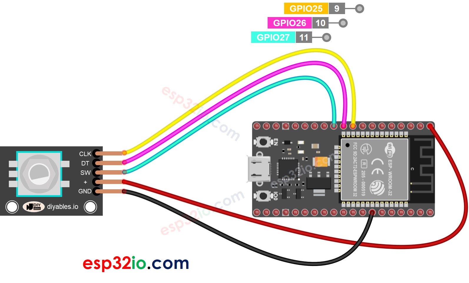
This image is created using Fritzing. Click to enlarge image
If you're unfamiliar with how to supply power to the ESP32 and other components, you can find guidance in the following tutorial: The best way to Power ESP32 and sensors/displays.
ESP32 Code – Rotary Encoder
The below ESP32 code does:
- Detects the direction and amount of rotation of the encoder.
- If detecting the knob turned by one detent (click) in clockwise direction, increase the counter by one.
- If detecting the knob turned by one detent (click) in anticlockwise direction, decrease the counter by one.
- Detects if the button is pressed.
To simplify the code for button debouncing, the ezButton library is used.
Quick Instructions
If this is the first time you use ESP32, see how to setup environment for ESP32 on Arduino IDE.
- Install ezButton library on Arduino IDE.
- Copy the above code and open with Arduino IDE
- Click Upload button on Arduino IDE to upload code to ESP32
- Turn the knob in clockwise, then anticlockwise
- Press the knob
- See the result on Serial Monitor.
Code Explanation
Check out the line-by-line comments in the code
ESP32 Code – Rotary Encoder with Interrupt
In the previous code, using polling to continuously check the pin's state can waste ESP32 resources and lead to missed counts if other code execution is slow.
An effective solution is to utilize the interrupt, which remove the necessity for polling. This enables the ESP32 to perform other tasks without missing the counts. The below is the ESP32 code that uses the interrupt to read the direction and position from the rotary encoder.
Now, As you turn the knob, you'll notice information appearing on the Serial Monitor, much like what you saw in the earlier code.
※ NOTE THAT:
- You might come across tutorials on other websites that use two interrupts for a single encoder, but this is unnecessary and wasteful. Just one interrupt is sufficient.
- It's important to use the volatile keyword for global variables used in the interrupt. Neglecting this could lead to unexpected issues.
- Keep the code within the interrupt as straightforward as you can. Avoid using Serial.print() or Serial.println() inside the interrupt.
ESP32 Rotary Encoder Application
With Rotary Encoder, we can do the following applications but not limit:
- ESP32 - Rotary Encoder controls Position of Sevo Motor
- ESP32 - Rotary Encoder controls Brightness of LED
- ESP32 - Rotary Encoder controls Speed of Stepper Motor
Video Tutorial
Making video is a time-consuming work. If the video tutorial is necessary for your learning, please let us know by subscribing to our YouTube channel , If the demand for video is high, we will make the video tutorial.