ESP32 - Rain Sensor - Relay
We are going to learn how to program ESP32 to activate the relay if the rain is detected.
Connecting the relay to a motor or actuator allows us to utilize the rain sensor for seamless control of the motor or actuator.
Hardware Used In This Tutorial
Or you can buy the following kits:
| 1 | × | DIYables ESP32 Starter Kit (ESP32 included) | |
| 1 | × | DIYables Sensor Kit (18 sensors/displays) |
Introduction to Relay and Rain Sensor
Unfamiliar with relay and rain sensor, including their pinouts, functionality, and programming? Explore comprehensive tutorials on these topics below:
Wiring Diagram
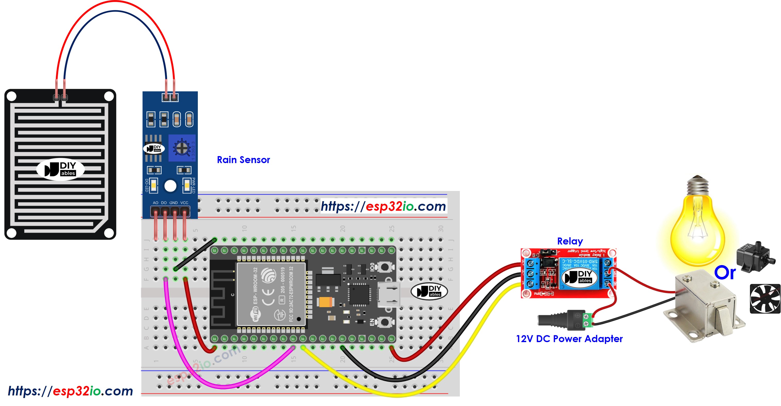
This image is created using Fritzing. Click to enlarge image
If you're unfamiliar with how to supply power to the ESP32 and other components, you can find guidance in the following tutorial: The best way to Power ESP32 and sensors/displays.
ESP32 Code
Quick Instructions
- If this is the first time you use ESP32, see how to setup environment for ESP32 on Arduino IDE.
- Do the wiring as above image.
- Connect the ESP32 board to your PC via a micro USB cable
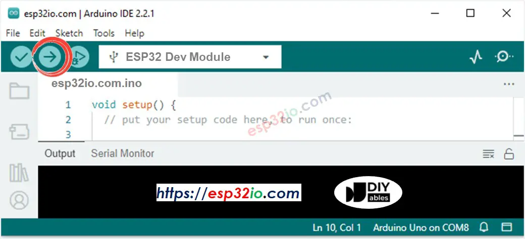
- Open Arduino IDE on your PC.
- Select the right ESP32 board (e.g. ESP32 Dev Module) and COM port.
- Connect ESP32 to PC via USB cable
- Open Arduino IDE, select the right board and port
- Copy the above code and open with Arduino IDE
- Click Upload button on Arduino IDE to upload code to ESP32
- Move your hand in front of sensor
- See the change of relay's state
Code Explanation
Read the line-by-line explanation in comment lines of source code!
Video Tutorial
Making video is a time-consuming work. If the video tutorial is necessary for your learning, please let us know by subscribing to our YouTube channel , If the demand for video is high, we will make the video tutorial.