ESP32 - Light Sensor Triggers Relay
This tutorial instructs you how to use ESP32, light sensor and relay to do a project that:
- Turns relay on if the analog value measured from light sensor's is below a threshold,
- Turns relay off if the analog value measured from light sensor's is above a threshold,
We can extend this tutorial to automatically turn on a led strip or light bulb when it is dark.
Hardware Used In This Tutorial
Or you can buy the following kits:
| 1 | × | DIYables ESP32 Starter Kit (ESP32 included) | |
| 1 | × | DIYables Sensor Kit (18 sensors/displays) |
The LDR light sensor is very affordable, but it requires a resistor for wiring, which can make the setup more complex. To simplify the wiring, you can use an LDR light sensor module as an alternative.
Introduction to Relay and Light Sensor
We have specific tutorials about relay and light sensor. Each tutorial contains detailed information and step-by-step instructions about hardware pinout, working principle, wiring connection to ESP32, ESP32 code... Learn more about them at the following links:
Wiring Diagram
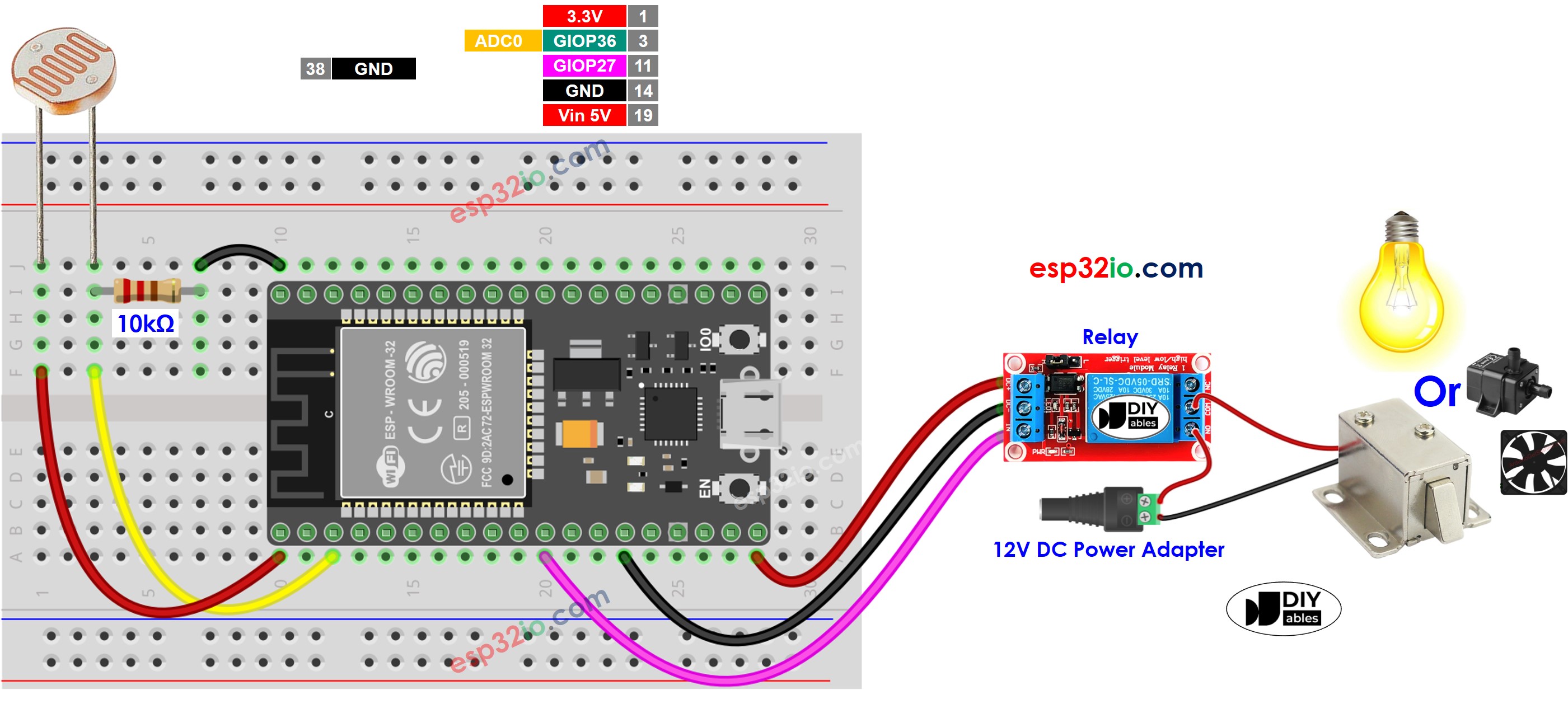
This image is created using Fritzing. Click to enlarge image
If you're unfamiliar with how to supply power to the ESP32 and other components, you can find guidance in the following tutorial: The best way to Power ESP32 and sensors/displays.
ESP32 Code
Quick Instructions
- If this is the first time you use ESP32, see how to setup environment for ESP32 on Arduino IDE.
- Do the wiring as above image.
- Connect the ESP32 board to your PC via a micro USB cable
- Open Arduino IDE on your PC.
- Select the right ESP32 board (e.g. ESP32 Dev Module) and COM port.
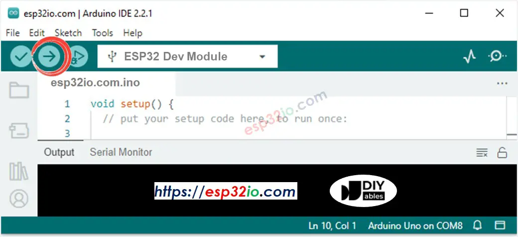
- Copy the above code and paste it to Arduino IDE.
- Compile and upload code to ESP32 board by clicking Upload button on Arduino IDE
- Radiates light to sensor
- See the change of relay's state
Line-by-line Code Explanation
The above ESP32 code contains line-by-line explanation. Please read the comments in the code!
※ NOTE THAT:
This tutorial uses the analogRead() function to read values from an ADC (Analog-to-Digital Converter) connected to a light sensor. The ESP32 ADC is good for projects that do NOT need high accuracy. However, for projects that need precise measurements, please note:
- The ESP32 ADC is not perfectly accurate and might need calibration for correct results. Each ESP32 board can be a bit different, so you need to calibrate the ADC for each individual board.
- Calibration can be difficult, especially for beginners, and might not always give the exact results you want.
For projects that need high precision, consider using an external ADC (e.g ADS1115) with the ESP32 or using an Arduino, which has a more reliable ADC. If you still want to calibrate the ESP32 ADC, refer to ESP32 ADC Calibration Driver
Video Tutorial
Making video is a time-consuming work. If the video tutorial is necessary for your learning, please let us know by subscribing to our YouTube channel , If the demand for video is high, we will make the video tutorial.