ESP32 - 2-Channel Relay Module
This tutorial provides step-by-step instructions on utilizing an ESP32 to control a 2-channel relay module. It covers the following aspects in detail:
- Understanding the pinout configuration of a 2-channel relay module
- Establishing the connections between an ESP32 and the 2-channel relay module
- Programming the ESP32 to effectively control the 2-channel relay module
When we need to control two high-voltage devices like pumps, fans, or actuators, we have two options. We can either use multiple relay modules or go for a more straightforward solution. The easier way is to use a 2-channel relay module, which is a single board with two relays built-in. This makes the setup simpler and more convenient for controlling both devices.
Hardware Used In This Tutorial
Or you can buy the following kits:
| 1 | × | DIYables ESP32 Starter Kit (ESP32 included) | |
| 1 | × | DIYables Sensor Kit (18 sensors/displays) |
Introduction to 2-Channel Relay Module
Pinout
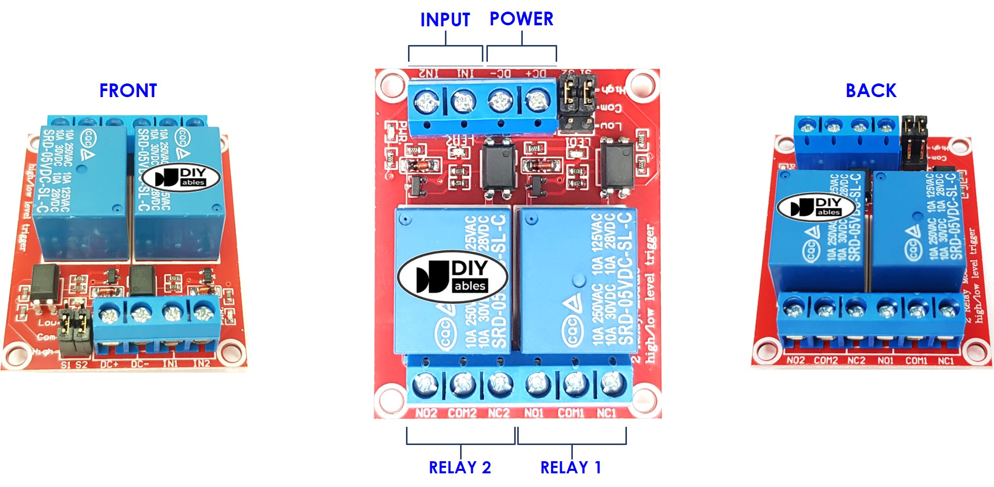
A 2-channel relay module has the following pins:
- Power pins for relay boards
- DC+: connect this pin to 5V pin of power supply
- DC-: connect this pin to the GND pin of the power supply and also to the GND pin of the ESP32
- Signal pins:
- IN1: this pin receives the control signal from ESP32 to control relay 1 on the module
- IN2: this pin receives the control signal from ESP32 to control relay 2 on the module
- Output pins: NCx (normally closed pin), NOx (normally open pin), COMx (common pin),
- NC1, NO1, COM1: These pins connect to a high-voltage device that is controlled by relay 1
- NC2, NO2, COM2: These pins connect to a high-voltage device that is controlled by relay 2
- Connecting relays to high-voltage devices
- Explaining the concepts of normally closed and normally open
- Describing the differences between low-level trigger and high-level trigger
- Demonstrating how to effectively control relays using ESP32
Moreover, the 2-channel relay module features two jumpers that grant you the flexibility to select either a low-level trigger or high-level trigger for each relay independently.
If you're keen on understanding the basics of relays, I highly recommend checking out the ESP32 - Relay tutorial. This tutorial offers comprehensive insights into:
Wiring Diagram
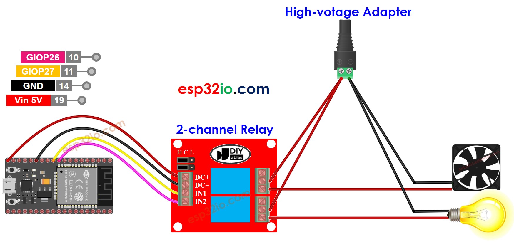
This image is created using Fritzing. Click to enlarge image
If you plan to use the 5V pins to power additional components, there's a chance that the relay module won't receive enough power. Therefore, it's essential to use a separate 5V power source specifically for the module.
So, we need to use three types of power sources:
- A 5V power adapter for ESP32
- A 5V power adapter for the 2-channel relay module
- One or several higher-voltage power adapters (12VDC, 24VDC, 48VDC, 220AC...) for things that are controlled by the 2-channel relay module
Below is the wiring diagram using three power sources. The power supply for the ESP32 (not shown in the image) can be connected either through a USB cable or a power jack.
This image is created using Fritzing. Click to enlarge image
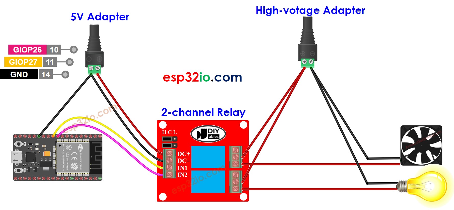
To reduce the number of power adapters required, we can simplify things by using a single 5V power supply for both the ESP32 and the 2-channel relay module.
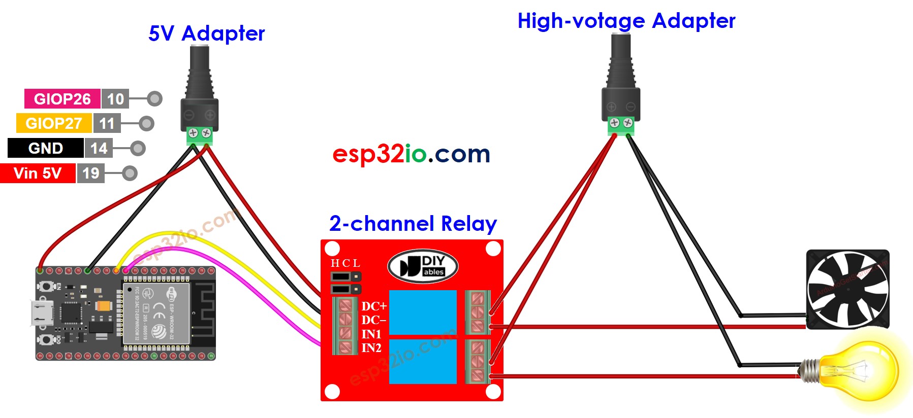
This image is created using Fritzing. Click to enlarge image
※ NOTE THAT:
If the two devices controlled by a 2-channel relay module operate at the same voltage, we can utilize a single high-voltage power adapter to supply power to both devices. However, if the devices require different voltages, we can independently use separate high-voltage power adapters for each device.
If you're unfamiliar with how to supply power to the ESP32 and other components, you can find guidance in the following tutorial: The best way to Power ESP32 and sensors/displays.
How To Program For 2-Channel Relay Module
- Initializes the ESP32 pin to the digital output mode by using pinMode() function.
- Control the relay's state by using digitalWrite() function.
ESP32 Code
Quick Instructions
- Copy the above code and open with Arduino IDE
- Click Upload button on Arduino IDE to upload code to ESP32
- Listen the click sound on relays.
- See the result on Serial Monitor.
Video Tutorial
Making video is a time-consuming work. If the video tutorial is necessary for your learning, please let us know by subscribing to our YouTube channel , If the demand for video is high, we will make the video tutorial.