ESP32 - Keypad - Electromagnetic Lock

In this tutorial, we are going to learn how to use a keypad, electromagnetic lock, and ESP32 together. In detail, If a user inputs the password on the keypad correctly, ESP32 turns the electromagnetic lock on.

The tutorial also provides the code that turns on a electromagnetic lock in a period of time and then turns off without using delay() function. The ESP32 code also supports multiple passwords.

Hardware Used In This Tutorial

1×ESP-WROOM-32 Dev Module
1×USB Cable Type-C
1×Keypad 3x4
1×Relay
1×Jumper Wires
1×Electromagnetic Lock
1×12V Power Adapter
1×(Optional) DC Power Jack
1×(Recommended) Screw Terminal Expansion Board for ESP32
1×(Recommended) Power Splitter For ESP32

Or you can buy the following sensor kits:

1×DIYables Sensor Kit (30 sensors/displays)
1×DIYables Sensor Kit (18 sensors/displays)
Disclosure: Some of the links in this section are Amazon affiliate links, meaning we may earn a commission at no additional cost to you if you make a purchase through them. Additionally, some links direct you to products from our own brand, DIYables.

Introduction to Keypad and Electromagnetic Lock

Unfamiliar with keypad and Electromagnetic Lock, including their pinouts, functionality, and programming? Explore comprehensive tutorials on these topics below:

Wiring Diagram

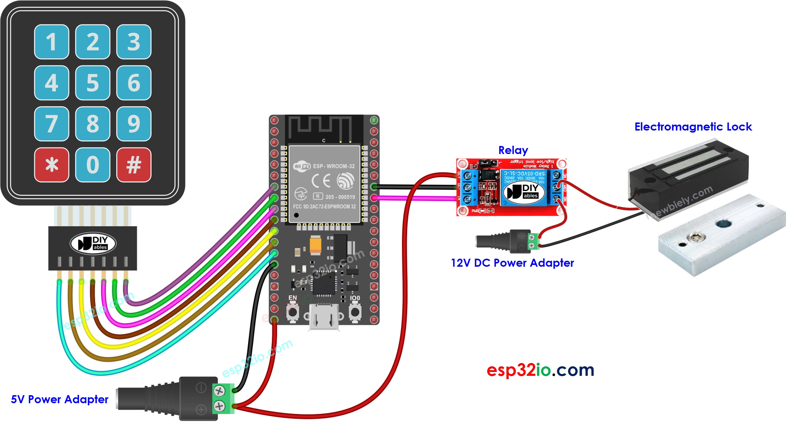
ESP32 keypad electromagnetic lock wiring diagram

This image is created using Fritzing. Click to enlarge image

If you're unfamiliar with how to supply power to the ESP32 and other components, you can find guidance in the following tutorial: How to Power ESP32.

ESP32 Code - turn electromagnetic lock on if the password is correct

The below codes turn a electromagnetic lock on if the password is correct

/* * This ESP32 code is created by esp32io.com * * This ESP32 code is released in the public domain * * For more detail (instruction and wiring diagram), visit https://esp32io.com/tutorials/esp32-keypad-electromagnetic-lock */ #include <Keypad.h> #define RELAY_PIN 19 // ESP32 pin GPIO19 connected to the relay #define ROW_NUM 4 // keypad four rows #define COLUMN_NUM 3 // keypad three columns char keys[ROW_NUM][COLUMN_NUM] = { {'1', '2', '3'}, {'4', '5', '6'}, {'7', '8', '9'}, {'*', '0', '#'} }; byte pin_rows[ROW_NUM] = {12, 14, 27, 26}; // ESP32 pin: GPIO12, GPIO14, GPIO27, GPIO26 connected to the row pins byte pin_column[COLUMN_NUM] = {25, 33, 32}; // ESP32 pin: GPIO25, GPIO33, GPIO32 connected to the column pins Keypad keypad = Keypad( makeKeymap(keys), pin_rows, pin_column, ROW_NUM, COLUMN_NUM ); const String password_1 = "1234"; // change your password here const String password_2 = "56789"; // change your password here const String password_3 = "901234"; // change your password here String input_password; void setup() { Serial.begin(9600); input_password.reserve(32); // maximum password size is 32, change if needed pinMode(RELAY_PIN, OUTPUT); // initialize pin as an output. digitalWrite(RELAY_PIN, HIGH); // lock the electromagnetic lock } void loop() { char key = keypad.getKey(); if (key) { Serial.println(key); if (key == '*') { input_password = ""; // reset the input password } else if (key == '#') { if (input_password == password_1 || input_password == password_2 || input_password == password_3) { Serial.println("The password is correct => unlock"); digitalWrite(RELAY_PIN, LOW); } else { Serial.println("The password is incorrect, try again"); } input_password = ""; // reset the input password } else { input_password += key; // append new character to input password string } } }

Quick Instructions

  • If this is the first time you use ESP32, see how to setup environment for ESP32 on Arduino IDE.
  • Do the wiring as above image.
  • Connect the ESP32 board to your PC via a micro USB cable
  • Open Arduino IDE on your PC.
  • Select the right ESP32 board (e.g. ESP32 Dev Module) and COM port.
  • Connect ESP32 to PC via USB cable
  • Open Arduino IDE, select the right board and port
  • Click to the Libraries icon on the left bar of the Arduino IDE.
  • Search “keypad”, then find the keypad library by Mark Stanley, Alexander Brevig
  • Click Install button to install keypad library.
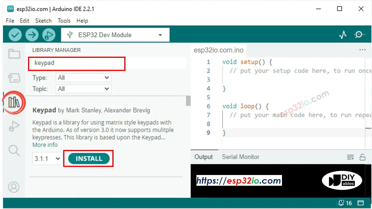
ESP32 keypad library
  • Copy the above code and open with Arduino IDE
  • Click Upload button on Arduino IDE to upload code to ESP32
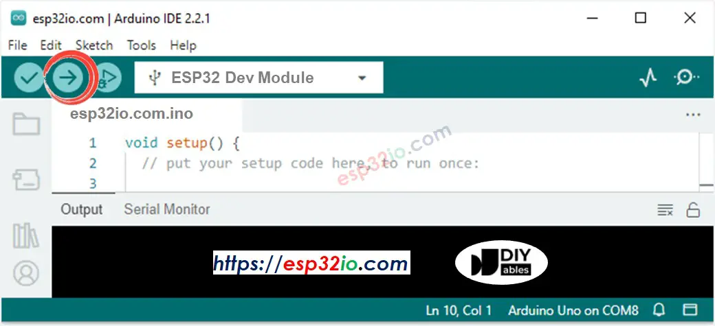
Arduino IDE Upload Code
  • Press 8123 keys and press #
  • Press 1234 keys and press #
  • See the result on Serial Monitor and the state of electromagnetic lock
COM6
Send
The password is incorrect, try again The password is correct => unlock
Autoscroll Show timestamp
Clear output
9600 baud  
Newline  

Code Explanation

Authorized passwords are pre-defined in the ESP32 code.

A string is used to store the password inputted by users, called input string. In keypad, two keys (* and #) are used for special purposes: clear password and terminate password. When a key on keypad is pressed:

  • If the pressed key is not two special keys, it is appended to the input string
  • If the pressed key is *, input string is clear. You can use it to start or re-start inputing the password
  • If the pressed key is #:
    • The input string is compared with the pre-defined passwords. If it matched with one of the pre-defined passwords, the electromagnetic lock is turned on.
    • No matter the password is correct or not, the input string is clear for the next input

ESP32 Code - turn a electromagnetic lock on in a period of time if the password is correct

The below code turns the electromagnetic lock on for 5 seconds if the password is correct. After 5 seconds, the electromagnetic lock is turned off.

/* * This ESP32 code is created by esp32io.com * * This ESP32 code is released in the public domain * * For more detail (instruction and wiring diagram), visit https://esp32io.com/tutorials/esp32-keypad-electromagnetic-lock */ #include <Keypad.h> #include <ezOutput.h> #define UNLOCK_TIME 5000 // in milliseconds #define RELAY_PIN 19 // ESP32 pin GPIO19 connected to the relay #define ROW_NUM 4 // keypad four rows #define COLUMN_NUM 3 // keypad three columns char keys[ROW_NUM][COLUMN_NUM] = { {'1', '2', '3'}, {'4', '5', '6'}, {'7', '8', '9'}, {'*', '0', '#'} }; byte pin_rows[ROW_NUM] = {12, 14, 27, 26}; // ESP32 pin: GPIO12, GPIO14, GPIO27, GPIO26 connected to the row pins byte pin_column[COLUMN_NUM] = {25, 33, 32}; // ESP32 pin: GPIO25, GPIO33, GPIO32 connected to the column pins Keypad keypad = Keypad( makeKeymap(keys), pin_rows, pin_column, ROW_NUM, COLUMN_NUM ); ezOutput relay(RELAY_PIN); const String password_1 = "1234"; // change your password here const String password_2 = "56789"; // change your password here const String password_3 = "901234"; // change your password here String input_password; void setup() { Serial.begin(9600); input_password.reserve(32); // maximum password size is 32, change if needed relay.high(); // lock the electromagnetic lock } void loop() { relay.loop(); // MUST call the loop() function first char key = keypad.getKey(); if (key) { Serial.println(key); if (key == '*') { input_password = ""; // reset the input password } else if (key == '#') { if (input_password == password_1 || input_password == password_2 || input_password == password_3) { Serial.println("The password is correct => unlock"); relay.high(); // set high before making a low pulse relay.pulse(UNLOCK_TIME); // deactivate the electromagnetic lock during UNLOCK_TIME duration } else { Serial.println("The password is incorrect, try again"); } input_password = ""; // reset the input password } else { input_password += key; // append new character to input password string } } }

Please note that, the above code use ezOutput library, which makes it easy to manage time in non-blocking maner. You can refer to ezOutput Library Installization Guide

Video Tutorial

Making video is a time-consuming work. If the video tutorial is necessary for your learning, please let us know by subscribing to our YouTube channel , If the demand for video is high, we will make the video tutorial.

※ OUR MESSAGES