Disclosure: Some of the links in this section are Amazon affiliate links, meaning we may earn a commission at no additional cost to you if you make a purchase through them. Additionally, some links direct you to products from our own brand, DIYables .
Introduction to RFID/NFC RC522 Module and Electromagnetic Lock
Unfamiliar with RFID/NFC RC522 Module and electromagnetic lock, including their pinouts, functionality, and programming? Explore comprehensive tutorials on these topics below:
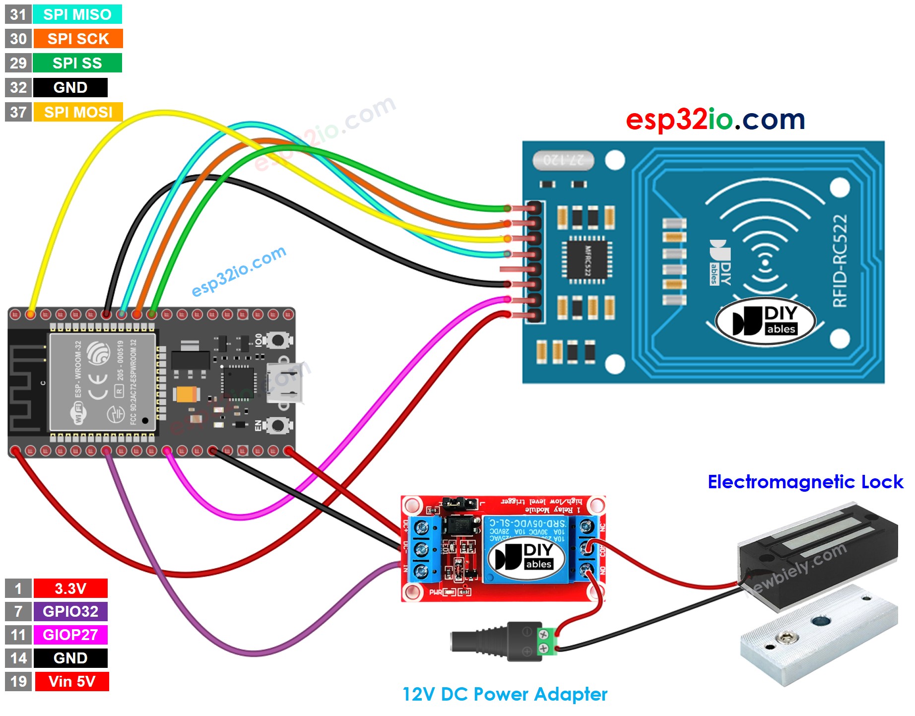
This image is created using Fritzing. Click to enlarge image
※ NOTE THAT:
The order of pins can vary according to manufacturers. ALWAYS use the labels printed on the module. The above image shows the pinout of the modules from DIYables manufacturer.
Connect the ESP32 board to your PC via a micro USB cable
Open Arduino IDE on your PC.
Select the right ESP32 board (e.g. ESP32 Dev Module) and COM port.
Because UID is usually not printed on RFID Tag, The first step we need to do is to find out the tag's UID. This can be done by:
Copy the above code and open with Arduino IDE
Click Upload button on Arduino IDE to upload code to ESP32
Open Serial Monitor
Tap an RFID Tag on RFID-RC522 module
Get UID on Serial Monitor
Newbiely | Arduino IDE 2.3.8
──
☐
✕
File
Edit
Sketch
Tools
Help
ESP32 Dev Module
Newbiely.ino
···
8Serial.println("Hello World!");
Output
Serial Monitor
Message (Enter to send message to 'ESP32 Dev Module' on 'COM15')
New Line
9600 baud
Tap RFID Tag on reader
Unauthorized Tag: 51 3D C1 AC
Ln 11, Col 1
ESP32 Dev Module on COM15
2
After having UID:
Update UID in the line 18 of the above code. For example, change byte authorizedUID[4] = {0xFF, 0xFF, 0xFF, 0xFF}; TO byte authorizedUID[4] = {0x51, 0x3D, 0xC1, 0xAC};
Upload the code to ESP32 again
Tap an RFID Tag on RFID-RC522 module
See output on Serial Monitor
Newbiely | Arduino IDE 2.3.8
──
☐
✕
File
Edit
Sketch
Tools
Help
ESP32 Dev Module
Newbiely.ino
···
8Serial.println("Hello World!");
Output
Serial Monitor
Message (Enter to send message to 'ESP32 Dev Module' on 'COM15')
New Line
9600 baud
Tap RFID Tag on reader
Authorized Tag
Ln 11, Col 1
ESP32 Dev Module on COM15
2
Tap another RFID Tag on RFID-RC522 module
See output on Serial Monitor
Newbiely | Arduino IDE 2.3.8
──
☐
✕
File
Edit
Sketch
Tools
Help
ESP32 Dev Module
Newbiely.ino
···
8Serial.println("Hello World!");
Output
Serial Monitor
Message (Enter to send message to 'ESP32 Dev Module' on 'COM15')
New Line
9600 baud
Tap RFID Tag on reader
Authorized Tag
Unauthorized Tag: 5D 11 1A D3
Ln 11, Col 1
ESP32 Dev Module on COM15
2
ESP32 Code - Multiple RFID Tags
We can allow multiple RFID/NFC tags to activate the electromagnetic lock. The below code uses two tags as an example.
/* * This ESP32 code is created by esp32io.com * * This ESP32 code is released in the public domain * * For more detail (instruction and wiring diagram), visit https://esp32io.com/tutorials/esp32-rfid-electromagnetic-lock */#include <SPI.h>#include <MFRC522.h>#define SS_PIN 5 // ESP32 pin GPIO5 #define RST_PIN 27 // ESP32 pin GPIO27 #define RELAY_PIN 32 // ESP32 pin GPIO32 controls the electromagnetic lock via therelayMFRC522 rfid(SS_PIN, RST_PIN);byte authorizedUID1[4] = {0x51, 0x3D, 0xC1, 0xAC};byte authorizedUID2[4] = {0x30, 0x01, 0x8B, 0x15}; voidsetup() {Serial.begin(9600);SPI.begin(); // init SPI bus rfid.PCD_Init(); // init MFRC522pinMode(RELAY_PIN, OUTPUT); // initialize pin as an output.digitalWrite(RELAY_PIN, LOW); // deactivate the electromagnetic lock => lockedSerial.println("Tap RFID Tag on reader");}voidloop() {if (rfid.PICC_IsNewCardPresent()) { // new tag is availableif (rfid.PICC_ReadCardSerial()) { // NUID has been readedMFRC522::PICC_Type piccType = rfid.PICC_GetType(rfid.uid.sak);if (rfid.uid.uidByte[0] == authorizedUID1[0] && rfid.uid.uidByte[1] == authorizedUID1[1] && rfid.uid.uidByte[2] == authorizedUID1[2] && rfid.uid.uidByte[3] == authorizedUID1[3] ) {Serial.println("Authorized Tag 1");digitalWrite(RELAY_PIN, LOW); // deactivate the electromagnetic lock => unlockeddelay(2000);digitalWrite(RELAY_PIN, HIGH); // activate the electromagnetic lock => locked }elseif (rfid.uid.uidByte[0] == authorizedUID2[0] && rfid.uid.uidByte[1] == authorizedUID2[1] && rfid.uid.uidByte[2] == authorizedUID2[2] && rfid.uid.uidByte[3] == authorizedUID2[3] ) {Serial.println("Authorized Tag 2");digitalWrite(RELAY_PIN, LOW); // deactivate the electromagnetic lock => unlockeddelay(2000);digitalWrite(RELAY_PIN, HIGH); // activate the electromagnetic lock => locked }else {Serial.print("Unauthorized Tag:");for (int i = 0; i < rfid.uid.size; i++) {Serial.print(rfid.uid.uidByte[i] < 0x10 ? " 0" : " ");Serial.print(rfid.uid.uidByte[i], HEX); }Serial.println(); } rfid.PICC_HaltA(); // halt PICC rfid.PCD_StopCrypto1(); // stop encryption on PCD } }}
Do the similar steps as the above, and then tap one by one tag on RFID-RC522 module. The result on Serial Monitor looks like below:
Newbiely | Arduino IDE 2.3.8
──
☐
✕
File
Edit
Sketch
Tools
Help
ESP32 Dev Module
Newbiely.ino
···
8Serial.println("Hello World!");
Output
Serial Monitor
Message (Enter to send message to 'ESP32 Dev Module' on 'COM15')
New Line
9600 baud
Tap RFID Tag on reader
Authorized Tag 2
Authorized Tag 1
Ln 11, Col 1
ESP32 Dev Module on COM15
2
Video Tutorial
Making video is a time-consuming work. If the video tutorial is necessary for your learning, please let us know by subscribing to our YouTube channel , If the demand for video is high, we will make the video tutorial.
Please feel free to share the link of this tutorial. However, Please do not use our content on any other websites. We invested a lot of effort and time to create the content, please respect our work!