ESP32 - LDR Module
The LDR light sensor module can sense and measure light around it. It has two outputs: a digital output that can be either LOW or HIGH, and an analog output.
In this tutorial, we will learn how to use an ESP32 and an LDR light sensor module together to detect and measure the amount of light. Here's what we'll cover:
- How to connect the LDR light sensor module to an ESP32.
- How to program the ESP32 to detect light by reading the digital signal from the LDR light sensor module.
- How to program the ESP32 to measure the light level by reading the analog signal from the LDR light sensor module.
Afterward, you can change the code to make an LED or a light bulb turn on (using a relay) when it senses light.
If you're interested in a light sensor in its raw form, I suggest exploring the tutorial for the ESP32 - Light Sensor.
This tutorial shows how to program the ESP32 using the Arduino language (C/C++) via the Arduino IDE. If you’d like to learn how to program the ESP32 with MicroPython, visit this ESP32 MicroPython - LDR Module tutorial.
Hardware Used In This Tutorial
Or you can buy the following kits:
| 1 | × | DIYables ESP32 Starter Kit (ESP32 included) | |
| 1 | × | DIYables Sensor Kit (18 sensors/displays) |
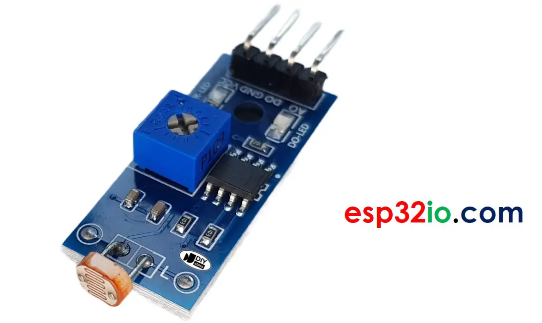
Introduction to LDR Light Sensor Module
The LDR light sensor module can be used to find out if there is light or how much light there is in the area around it. It has a digital output pin and an analog output pin for different options.
Pinout
The LDR light sensor module has four pins:
- VCC pin: Connect this pin to the power source (between 3.3V to 5V).
- GND pin: Connect this pin to the ground (0V).
- DO pin: This is a digital output pin. It gives a HIGH signal when it's dark and LOW when it's light. You can adjust the threshold between dark and light using a built-in potentiometer.
- AO pin: This is an analog output pin. The value decreases as the light gets brighter and increases as the light gets darker.
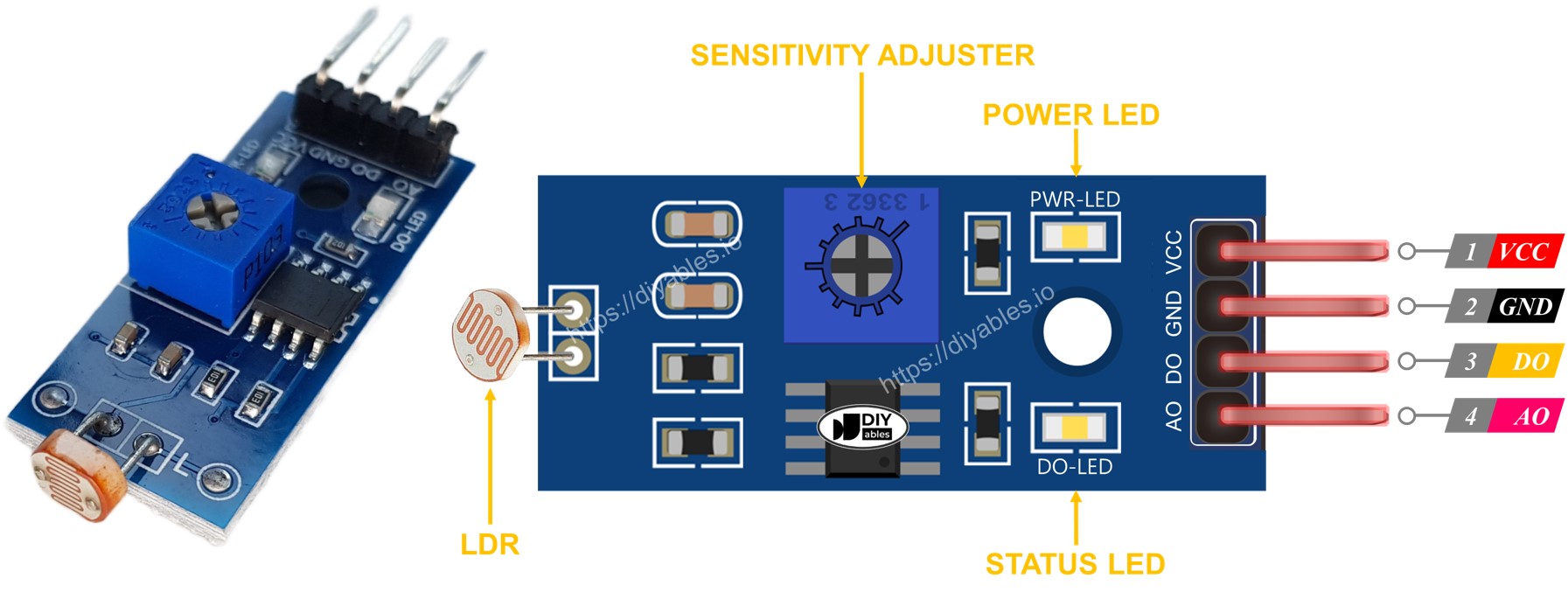
Additionally, the LDR light sensor module is equipped with two LED indicators:
- The PWR-LED indicator shows the power status.
- The DO-LED indicator reflects the state of light on the DO pin: it illuminates when there is light and remains off when it is dark.
How It Works
Regarding the DO pin:
- The LDR light sensor module has a potentiometer that allows you to adjust the sensitivity or threshold for detecting light.
- When the light intensity in the surrounding environment is above the set threshold (considered as light), the output of the sensor on the DO pin becomes LOW, and the DO-LED turns on.
- When the light intensity in the surrounding environment is below the set threshold (considered as dark), the output of the sensor on the DO pin becomes HIGH, and the DO-LED turns off.
Regarding the AO pin:
- The value read from the AO pin is inversely proportional to the light intensity in the surrounding environment. In other words, as the light intensity increases (brighter), the value on the AO pin decreases.
- Similarly, as the light intensity decreases (darker), the value on the AO pin increases.
It's important to note that adjusting the potentiometer does not affect the value on the AO pin.
Wiring Diagram
The light sensor module offers two outputs, DO and AO, which can be used individually or together.
- How to connect ESP32 and ldr module using breadboard
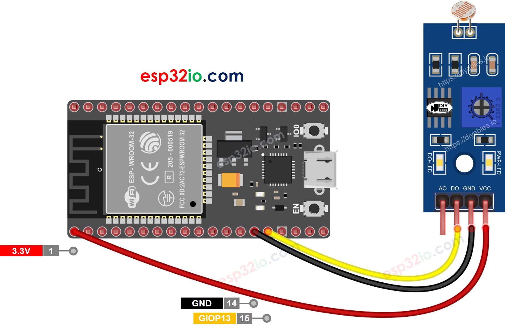
This image is created using Fritzing. Click to enlarge image
- How to connect ESP32 and ldr module using screw terminal block breakout board
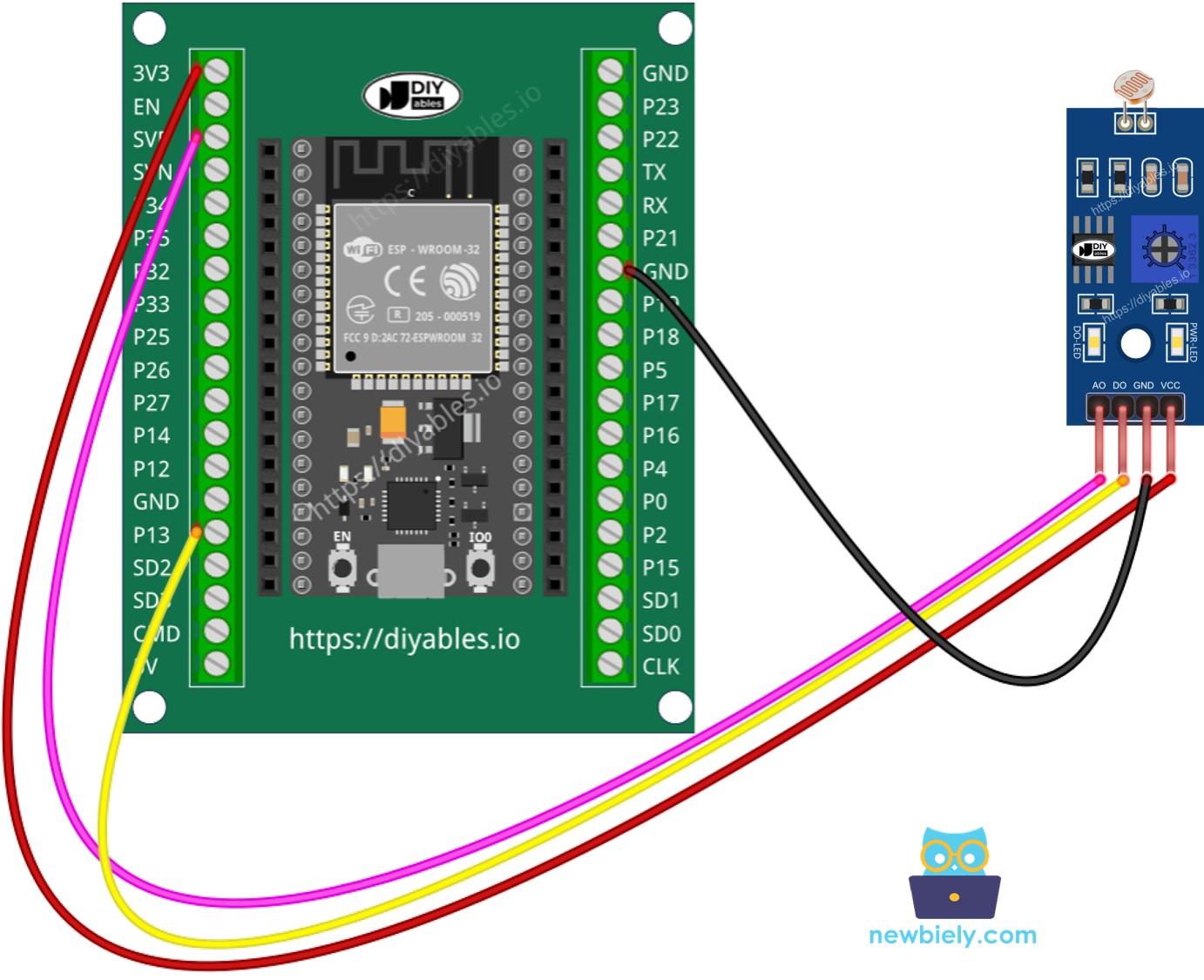
If you're unfamiliar with how to supply power to the ESP32 and other components, you can find guidance in the following tutorial: The best way to Power ESP32 and sensors/displays.
ESP32 Code - Read value from DO pin
Quick Instructions
- If this is the first time you use ESP32, see how to setup environment for ESP32 on Arduino IDE.
- Do the wiring as above image.
- Connect the ESP32 board to your PC via a micro USB cable
- Open Arduino IDE on your PC.
- Select the right ESP32 board (e.g. ESP32 Dev Module) and COM port.
- Copy the above code and open with Arduino IDE
- Click Upload button on Arduino IDE to upload code to ESP32
- Cover and uncover the LDR light sensor module by your hand or something
- See the result on Serial Monitor.
If you observe that the LED status remains constantly on or off, regardless of the presence of light, you have the option to adjust the potentiometer. This adjustment allows you to finely tune the light sensitivity of the sensor.
Furthermore, the code can be modified according to your requirements. For instance, you can program the LED to activate or the light to turn on when light is detected. Additionally, you have the flexibility to make a servo motor rotate. Detailed instructions and tutorials on these customization options can be found at the end of this guide.
ESP32 Code - Read value from AO pin
Quick Instructions
- Copy the above code and open with Arduino IDE
- Click Upload button on Arduino IDE to upload code to ESP32
- Cover and uncover the LDR light sensor module by your hand or something
- See the result on Serial Monitor.
※ NOTE THAT:
This tutorial uses the analogRead() function to read values from an ADC (Analog-to-Digital Converter) connected to a LDR module. The ESP32 ADC is good for projects that do NOT need high accuracy. However, for projects that need precise measurements, please note:
- The ESP32 ADC is not perfectly accurate and might need calibration for correct results. Each ESP32 board can be a bit different, so you need to calibrate the ADC for each individual board.
- Calibration can be difficult, especially for beginners, and might not always give the exact results you want.
For projects that need high precision, consider using an external ADC (e.g ADS1115) with the ESP32 or using an Arduino, which has a more reliable ADC. If you still want to calibrate the ESP32 ADC, refer to ESP32 ADC Calibration Driver
Video Tutorial
Making video is a time-consuming work. If the video tutorial is necessary for your learning, please let us know by subscribing to our YouTube channel , If the demand for video is high, we will make the video tutorial.