ESP32 - Rain Sensor
The rain sensor is capable of detecting and measuring rain/snow level. The rain sensor provides two outputs: a digital output (LOW/HIGH) and an analog output.
In this tutorial, we will learn how to use an ESP32 and an rain sensor to detect and measure the rain. Specifically, we will cover the following:
- How to connect the rain sensor to an ESP32.
- How to program the ESP32 to detect the rain by reading the digital signal from the rain sensor.
- How to program the ESP32 to measure the rain level by reading the analog signal from the rain sensor.
Afterward, you can modify the code to activate a motor or warning when it detects rain./snow
This tutorial shows how to program the ESP32 using the Arduino language (C/C++) via the Arduino IDE. If you’d like to learn how to program the ESP32 with MicroPython, visit this ESP32 MicroPython - Rain Sensor tutorial.
Hardware Used In This Tutorial
Or you can buy the following kits:
| 1 | × | DIYables ESP32 Starter Kit (ESP32 included) | |
| 1 | × | DIYables Sensor Kit (18 sensors/displays) |
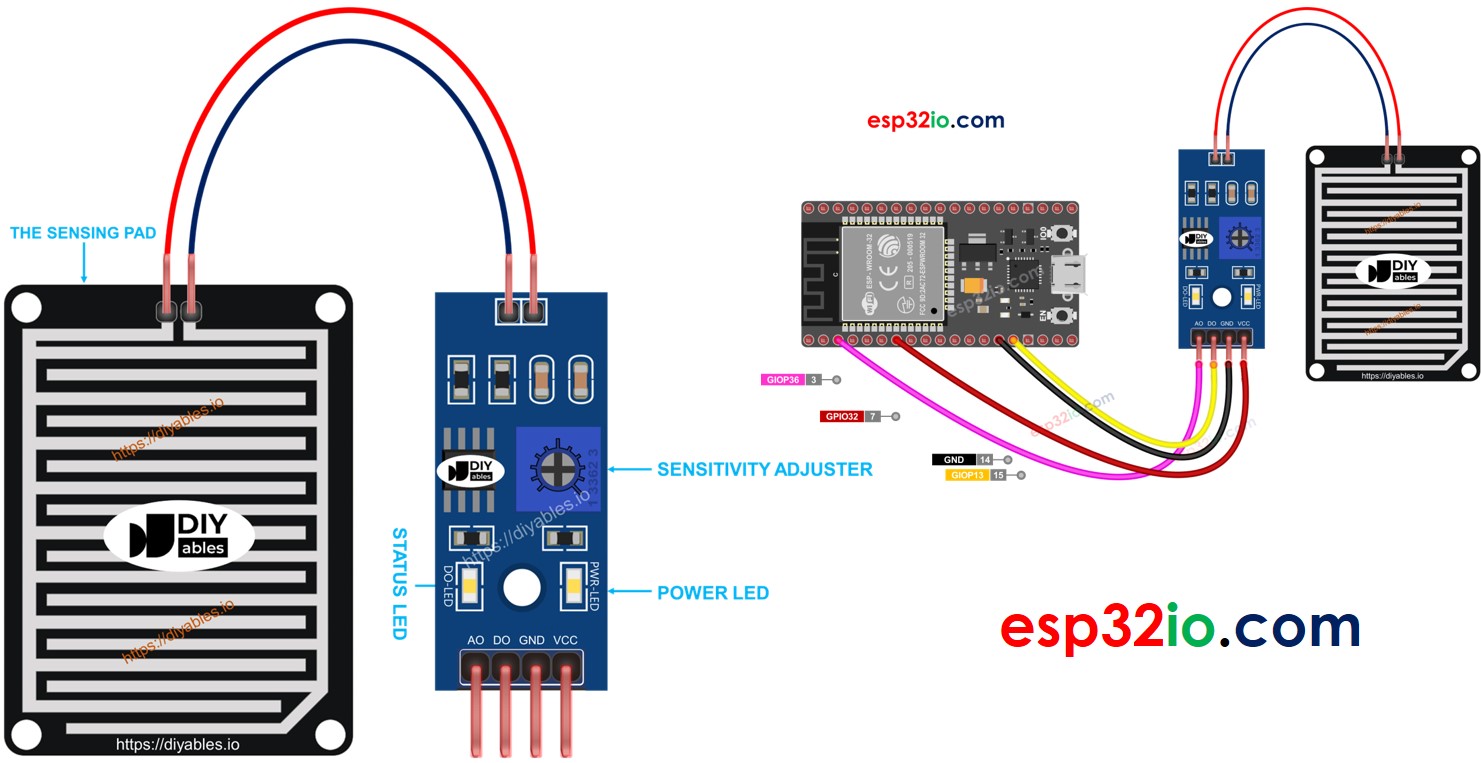
Introduction to Rain Sensor
The rain sensor can be utilized to detect the presence of rain or measure the level of water dropped by the rain. The rain sensor provides two options via a digital output pin and analog output pin.
The rain sensor includes two parts:
- The sensing pad
- The electronic module
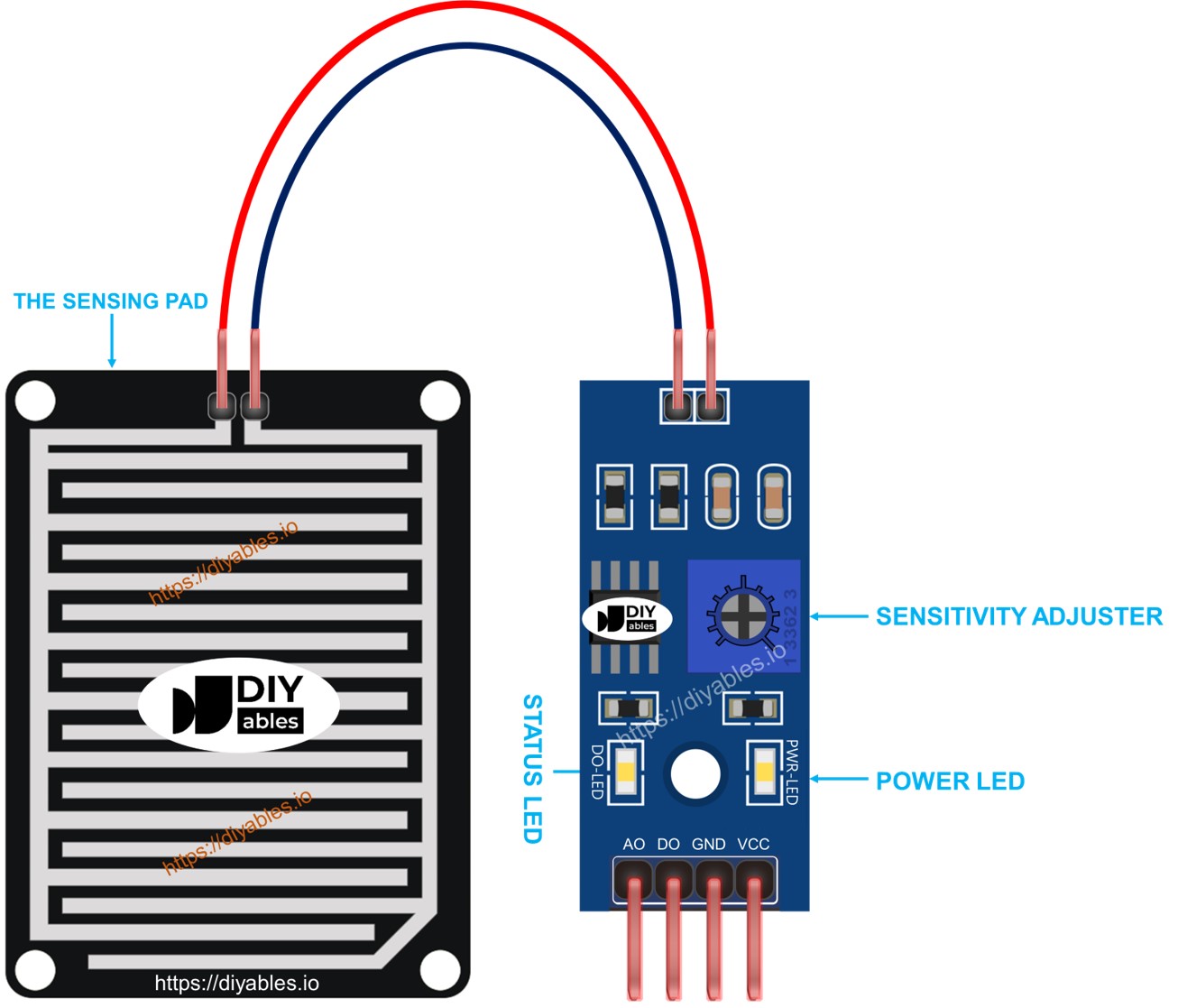
The sensing pad
The sensing pad is placed outside that can face with rain/snow (e.g. the roof). The sensing pad has a series of exposed copper traces, devided into two groups: power traces and sense traces. These power traces and sense traces are not connected unless they are bridged by water or snow. There is no differences between the power trace and sense trace. You can pick one as power trace and the other wil be come the sense trace
The electronic module
The The electronic module of rain sensor converts the signal from the sensing pad to analog or digital value that can be read by ESP32. It includes four pins:
- VCC pin: It needs to be connected to VCC (3.3V to 5V).
- GND pin: It needs to be connected to GND (0V).
- DO pin: It is a digital output pin. It is HIGH if the rain is not detected and LOW if detected. The threshold value for rain detection can be adjusted using a built-in potentiometer.
- AO pin: It is an analog output pin. The output value decreases as the water in the sensing pad is increased, and it increases as water in the sensing pad is decreased.
Furthermore, it has two LED indicators:
- One PWR-LED indicator for power.
- One DO-LED indicator for the rain state on the DO pin: it is on when rain is present.
How It Works
For the DO pin:
- The module has a built-in potentiometer for setting the threshold (sensitivity).
- When the intensity is above the threshold value, the rain is detected, the output pin of the sensor is LOW, and the DO-LED is on.
- When the intensity is below the threshold value, the rain is NOT detected, the output pin of the sensor is HIGH, and the DO-LED is off.
For the AO pin:
- The more water in the sensing pad, the lower the value read from the AO pin.
- The less water in the sensing pad, the higher the value read from the AO pin.
Note that the potentiometer does not affect the value on the AO pin.
Wiring Diagram
As mentioned above, the VCC pin of the sensor should be connected to the 3.3V or 5V. If we connect this pin directly to 3.3V or 5V pin of ESP32, the lifespan of sensor will be shorten because of electrochemical corrosion. The best way is to connect the the VCC pin of the rain sensor to an output pin of ESP32, We can program that pin to power the rain sensor when reading only. This can mimimize the impart of the electrochemical corrosion.
Since the rain sensor module has two outputs, you can choose to use one or both of them, depending on what you need.
- How to connect ESP32 and rain sensor using breadboard
The rain sensor module offers two outputs. You can use either one or both as required.
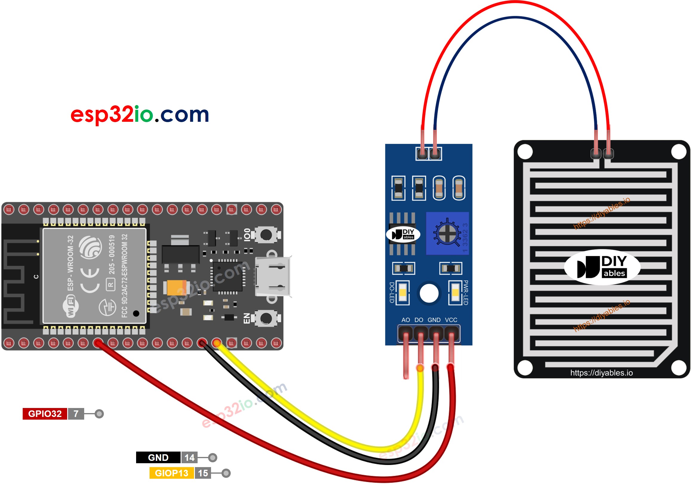
This image is created using Fritzing. Click to enlarge image
- How to connect ESP32 and rain sensor using screw terminal block breakout board
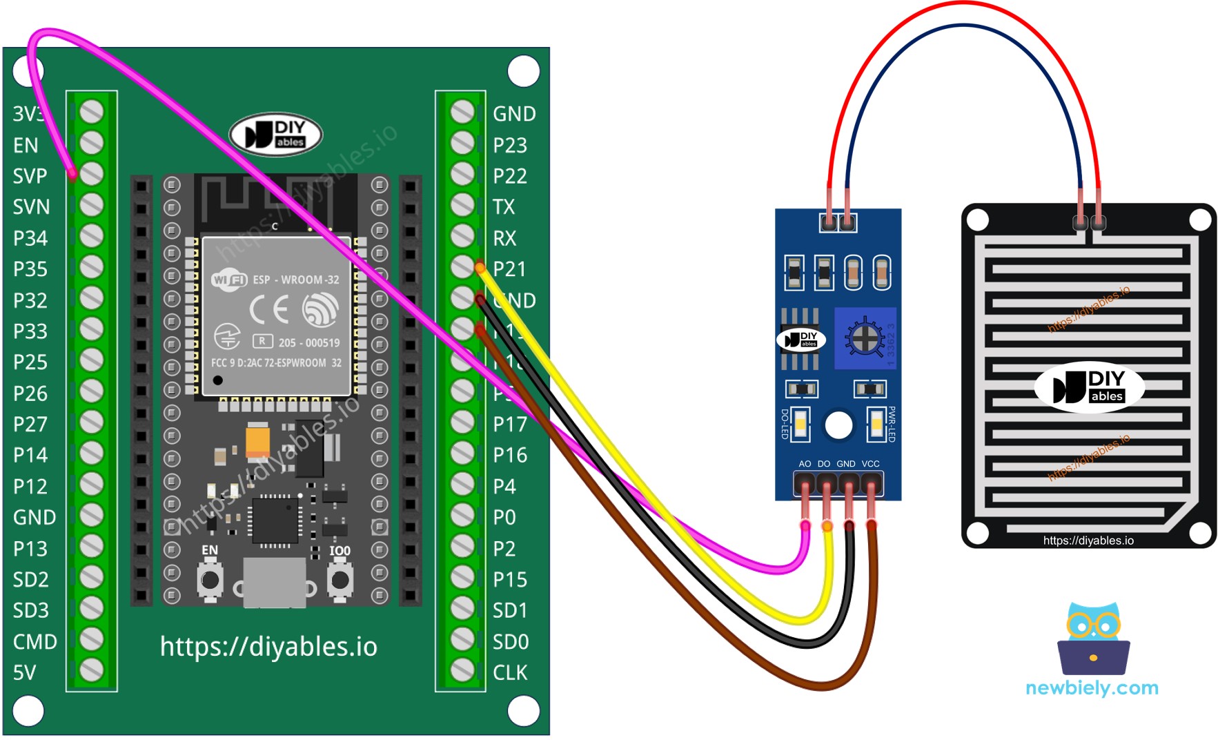
If you're unfamiliar with how to supply power to the ESP32 and other components, you can find guidance in the following tutorial: The best way to Power ESP32 and sensors/displays.
ESP32 Code - Read value from DO pin
Quick Instructions
- If this is the first time you use ESP32, see how to setup environment for ESP32 on Arduino IDE
- Copy the above code and open with Arduino IDE
- Click Upload button on Arduino IDE to upload code to ESP32
- Drop some water to the rain sensor
- See the result on Serial Monitor.
Please keep in mind that if you notice the LED status remaining on constantly or off even when the sensor faces to a rain, you can adjust the potentiometer to fine-tune the sensitivity of the sensor.
ESP32 Code - Read value from AO pin
Quick Instructions
- Copy the above code and open with Arduino IDE
- Click Upload button on Arduino IDE to upload code to ESP32
- Drop some water to the rain sensor
- See the result on Serial Monitor.
※ NOTE THAT:
This tutorial uses the analogRead() function to read values from an ADC (Analog-to-Digital Converter) connected to a rain sensor. The ESP32 ADC is good for projects that do NOT need high accuracy. However, for projects that need precise measurements, please note:
- The ESP32 ADC is not perfectly accurate and might need calibration for correct results. Each ESP32 board can be a bit different, so you need to calibrate the ADC for each individual board.
- Calibration can be difficult, especially for beginners, and might not always give the exact results you want.
For projects that need high precision, consider using an external ADC (e.g ADS1115) with the ESP32 or using an Arduino, which has a more reliable ADC. If you still want to calibrate the ESP32 ADC, refer to ESP32 ADC Calibration Driver
Video Tutorial
Making video is a time-consuming work. If the video tutorial is necessary for your learning, please let us know by subscribing to our YouTube channel , If the demand for video is high, we will make the video tutorial.