ESP32 - Modbus
This tutorial instructs you how to use ESP32 with Modbus protocol
Introduction to Modbus
Modbus is a protocol that enables communicattion from device to device, device to software/app, and devices to HMI. It is widely used in industrial devices.
We can imagine that Modbus is a communication language between devices, software/app, and HMI.
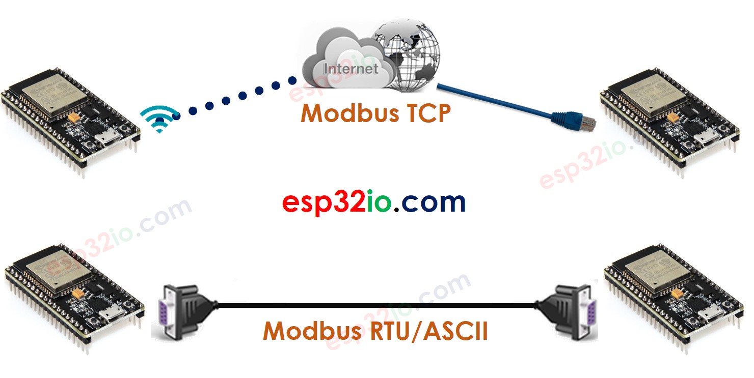
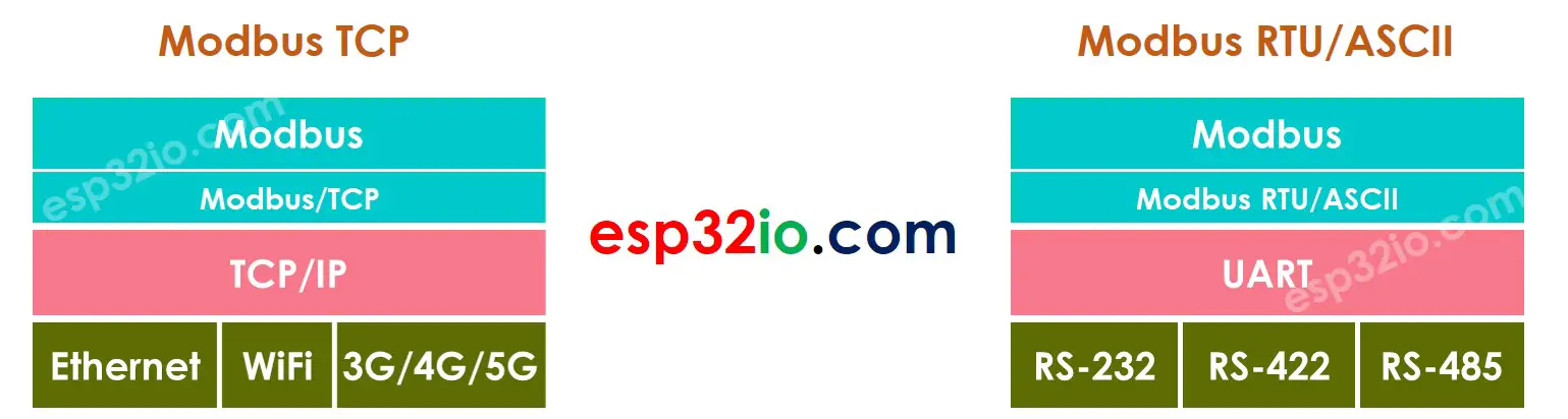
There are three wide-used Modbus types: Modbus RTU, Modbus ASCII, and Modbus TCP:
- Modbus RTU and Modbus ASCII are used over Serial line (RS-232/RS-422/RS-485)
- Modbus TCP is used over Ethernet or WiFi
Why use Modbus?
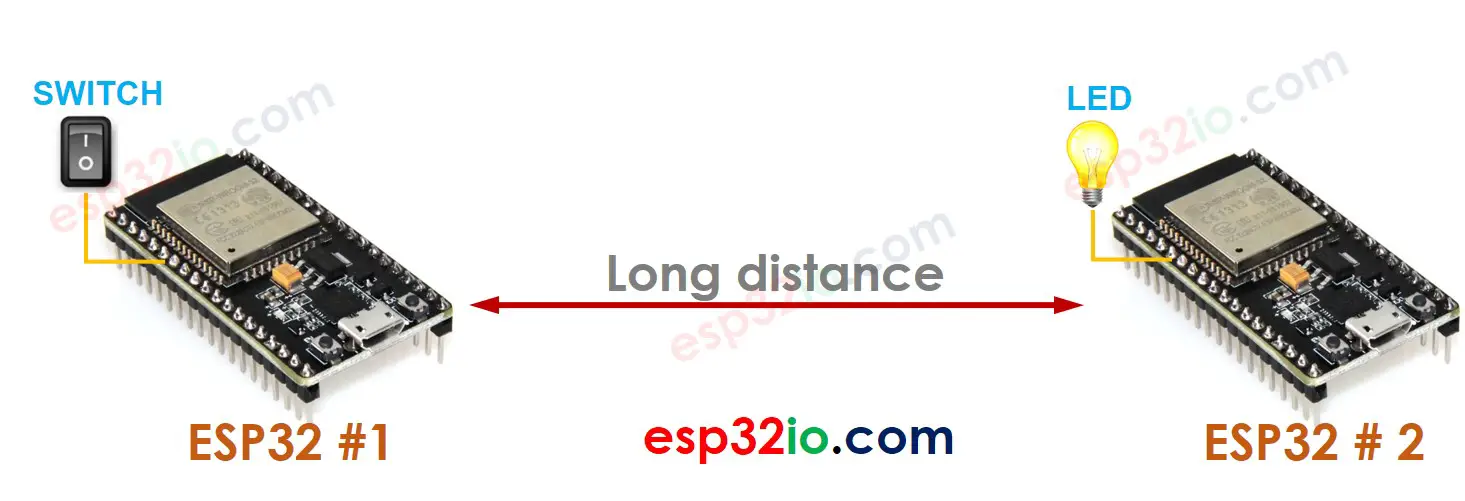
Let's take a specific case for example:
- An ESP32 #1 connected to a switch
- An ESP32 #2 connected to a LED
- ESP32 #1 and ESP32 #2 is far from each other
- When the switch is switched to ON, turn the LED on.
- When the switch is switched to OFF, turn the LED OFF.
The easiest way to implement the above example is to define a simple protocol by ourselves:
- ESP32 #1 send one byte of data to inform ESP32 #1 about the change on the state of switch. The value of the data byte is:
- 1: When the switch is switched to ON
- 0: When the switch is switched to OFF
- When ESP32 #2 receives a byte of data from ESP32 #1, if the value is:
- 1: Turn LED on
- 0: Turn LED off
- ESP32 #1 wants to get confirmed if the command is received and executed successfully by ESP32 #2 or not
- ESP32 #1 wants to control multiple LEDs on ESP32 #2
- ESP32 #2 wants to actively read the switches's state on ESP32 #1
- ESP32 #2 wants to use a switch to control an LED on ESP32 #1
- And more and more cases.
- We do NOT need to define the commands, Modbus defined it for all use cases.
- ESP32 can work with any devices/software that uses Modbus.
The above definition make the switch on ESP32 #1 control LED on ESP32 #2. However, let's imagine some cases:
It is not easy to suppport all use cases by ourselves.
Another problem occurs when using a protocol by ourselves. ESP32 cannot communicate with other devices that use another protocol.
⇒ We needs a standard protocol that solve all of above the issues ⇒ Modbus protocol is a standard protocol that we can use.
The advantage of the Modbus protocol over self-defined protocol:
When should use and should NOT use Modbus
Because the Modbus protocol is not easy to understand and implement it, even the Modbus library is available. You can use a simple self-defined protocol as described above when:
- The system is simple, such a switch on ESP32 #1 controls a LED on ESP32 #2
- ESP32 does NOT need to work with other devices/software
We should use Modbus when:
- The system is complicated
- The system requires the high reliability
- ESP32 needs to work with other devices/software
How Modbus protocol works
Concepts
There are six important concepts in Modbus:
- Master and Slave
- Request and Response
- Function Code (FC) and Address
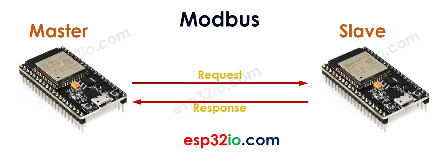
When two ESP32 communicate with each other using Modbus:
- One ESP32 work as a Master
- The other ESP32 works as a Slave.
The Master sends a request to the Slave, and the Slave sends a response to the Master.
A request sent from a Master to a Slave contains the below information:
- Function Code (FC): 1 byte, is the command that tells the Slave what to do. For example, reads the state of a digital input pin, a digital output pin or analog input pin, controls a digital output pin.
- Address: 2 bytes, is address that tells the Slave where to do. For example, Each digital input/output and analog input pins are given an uniqueaddress.
- Data (e,g control value)
When receiving a request from a Master, the Slave takes the corresponding action and send back the result on a response
Function Code
The Modbus standard defines many Function Code. To avoid overloading newbies, Let's some essential Function Code:
- FC 01 (Read Coils): is a command that reads the state of digital output pins
- FC 02 (Read Discrete Inputs): is a command that reads the state of digital input pins
- FC 05 (Write Single Coil): is a command that controls (write) the state of digital output pins
FC 01 indicates the Function Code's value is 0x01.
When using ESP32 Modbus library, you need to determine:
- Which Function Code to use
- Which address to use
Let's realize the example we mentioned at the beginning:
- ESP32 Master is wired to LED #M, SWITCH #M
- ESP32 Slave is wired to LED #S, SWITCH #S
- Let's make SWITCH #M control LED #S, and SWITCH #S control LED #M
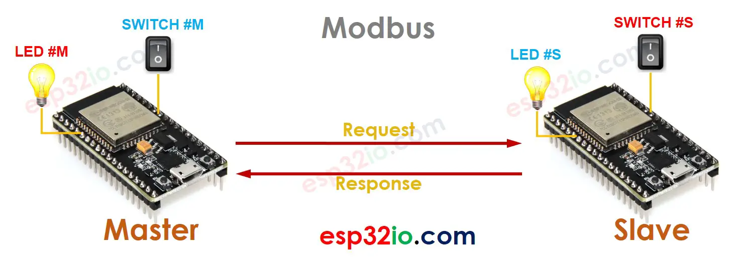
How to do:
- ESP32 Master reads the state of SWITCH #M → send a request to Slave to control LED #S ⇒ Slave controls LED #S and send the response
- ESP32 Master sends a request Slave to read the state of SWITCH #S ⇒ Slave responds with state of SWITCH #S → Master controls LED #M
Modbus RTU/ASCII and Modbus TCP
As mentioned at the beginning, There are 3 wide-used Modbus types: Modbus RTU, Modbus ASCII, and Modbus TCP.
- System diagram
- Protocol stack
The Modbus library for ESP32 is available. The detailed instruction of using the Modbus library will be presented in another tutorial, like our Facebook page to get the update.