ESP32 - Siren
In this tutorial, we are going to learn how to program ESP32 to control a siren to produce a warning sound and/or light.
Hardware Used In This Tutorial
Or you can buy the following kits:
| 1 | × | DIYables ESP32 Starter Kit (ESP32 included) | |
| 1 | × | DIYables Sensor Kit (18 sensors/displays) |
Introduction to Siren
Depending on the manufacturer, a siren can produce either a loud sound or a warning light, making it suitable for an alarm system. It is also available in several operating voltages. This tutorial will use a 12V siren, and other voltages will be similar.
Pinout
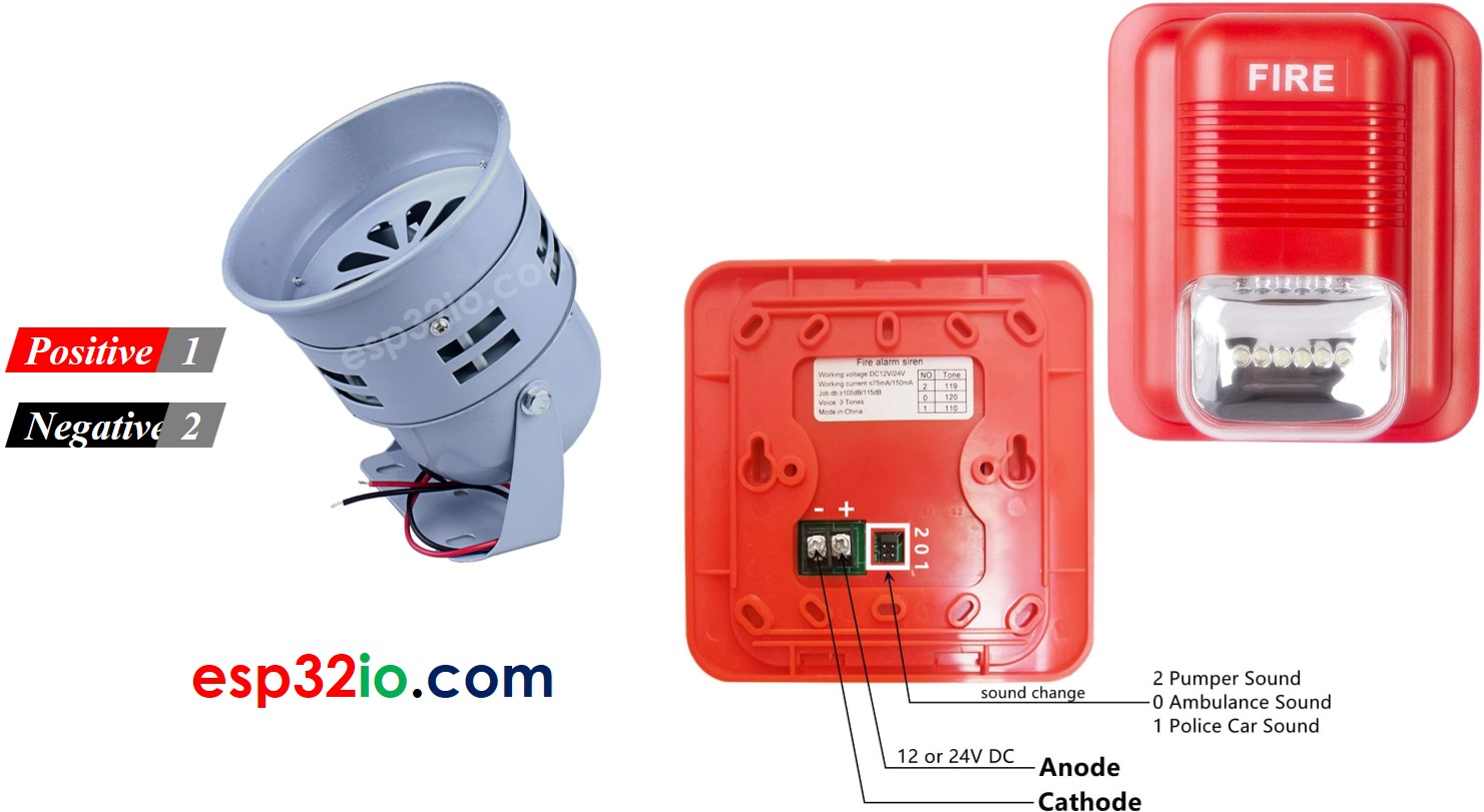
12V siren usually has two pins:
- Negative (-) pin (black): needs to be connected to GND of DC power supply
- Positive (+) pin (red): needs to be connected to 12V of DC power supply
How to Control a Siren
If 12V siren is powered by 12V power supply, it make sound and/or warning light. To control a 12V siren, we need to use a relay in between ESP32 and 12V siren. ESP32 can control the 12V siren via the relay. If you do not know about relay (pinout, how it works, how to program ...), learn about relay in the ESP32 - Relay tutorial
Wiring Diagram
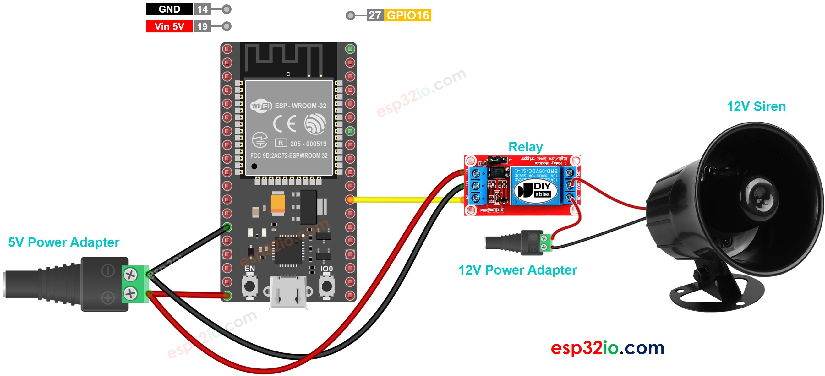
This image is created using Fritzing. Click to enlarge image
If you're unfamiliar with how to supply power to the ESP32 and other components, you can find guidance in the following tutorial: The best way to Power ESP32 and sensors/displays.
ESP32 Code
The below code repeatedly turns the 12V siren ON in three seconds and OFF in five seconds,
Quick Instructions
- If this is the first time you use ESP32, see how to setup environment for ESP32 on Arduino IDE
- Connect ESP32 to PC via USB cable
- Open Arduino IDE, select the right board and port
- Copy the above code and open with Arduino IDE
- Click Upload button on Arduino IDE to upload code to ESP32
- Check out the siren's state
Code Explanation
Read the line-by-line explanation in comment lines of code!
Video Tutorial
Making video is a time-consuming work. If the video tutorial is necessary for your learning, please let us know by subscribing to our YouTube channel , If the demand for video is high, we will make the video tutorial.