
ESP32 - 10 Segment LED Bar Graph
Or you can buy the following kits:
| 1 | × | DIYables ESP32 Starter Kit (ESP32 included) | |
| 1 | × | DIYables ESP32 S3 Starter Kit (ESP32 S3 included) | |
| 1 | × | DIYables Sensor Kit (18 sensors/displays) |
This tutorial instructs you how to use ESP32 to control a 10 Segment LED Bar Graph and display a visual bar animation on the display.
Introduction to 10 Segment LED Bar Graph
| 10 Segment LED Bar Graph | |
|---|---|
| The number of segments | 10 |
| The LED color | Bright red |
| The forward voltage | ~2V per segment |
| The forward current | 20mA max per segment |
| The required resistor | 220Ω per segment |
LED Bar Graph Pinout
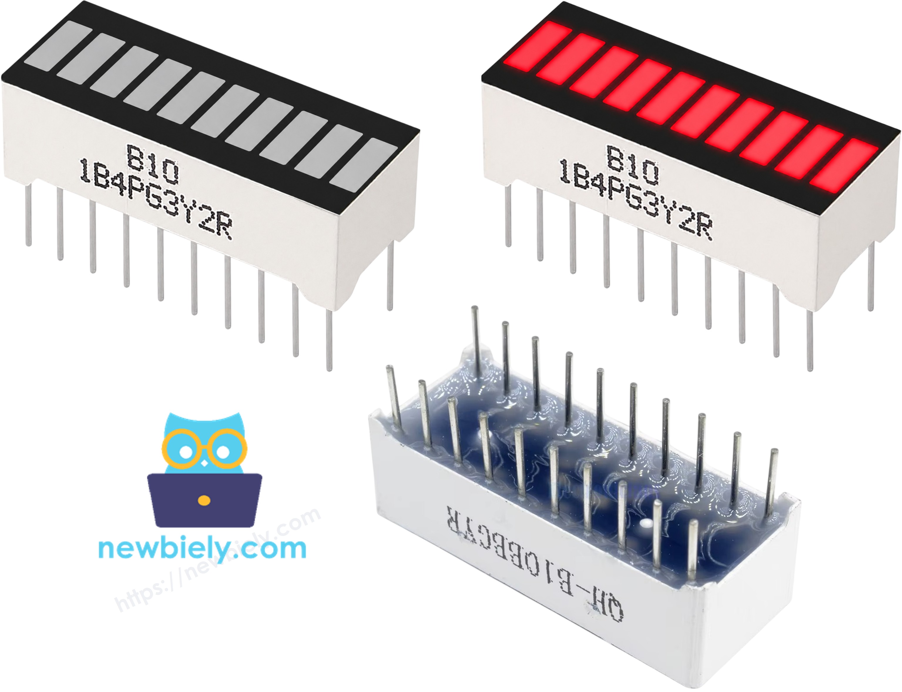
- Anode pins (A1–A10): connect these pins to GPIO pins via 220Ω resistors
- Cathode pins (K1–K10): connect these pins to GND (0V)
We highly recommend connecting current-limiting resistors on every anode to protect the ESP32 GPIO pins.
※ NOTE THAT:
All 10 anode pins are wired down a single side of the ESP32 Dev Board header, in physical pin order, to keep the wiring straightforward. This does mean GPIO5 and GPIO15 are used — both only briefly pulse at boot and are commonly used for onboard LEDs, so they're low-risk. GPIO0, GPIO2, and GPIO12, which can actually interfere with the board's boot or flashing mode, are avoided entirely.
Wiring Diagram between 10 Segment LED Bar Graph and ESP32
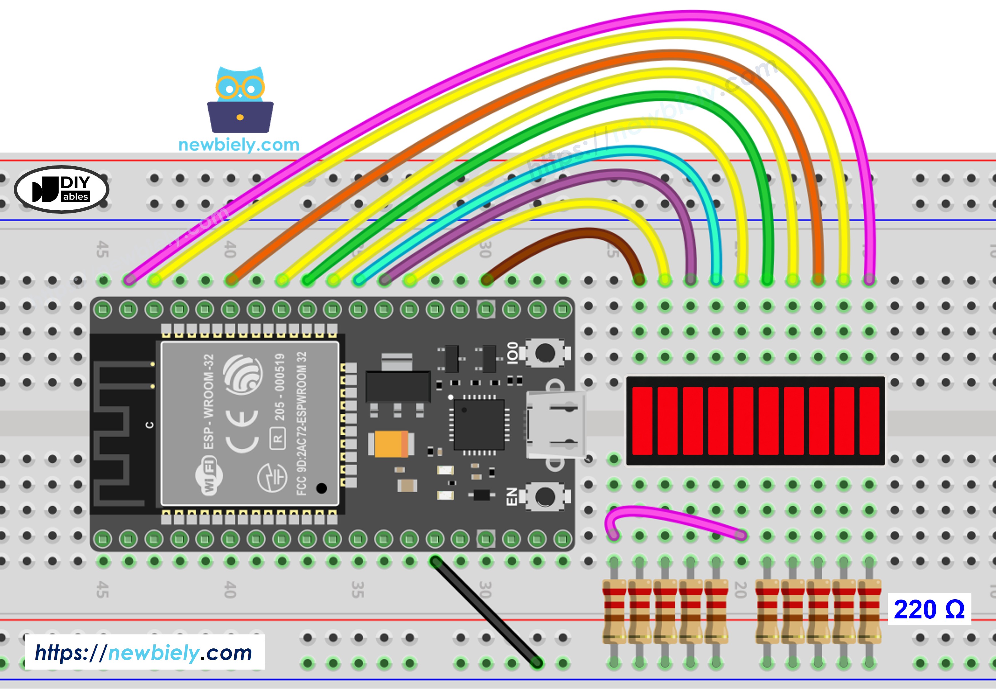
This image is created using Fritzing. Click to enlarge image
| LED Bar Graph | ESP32 Pin |
|---|---|
| A1 (Anode 1) | GPIO23 (via 220Ω) |
| A2 (Anode 2) | GPIO22 (via 220Ω) |
| A3 (Anode 3) | GPIO21 (via 220Ω) |
| A4 (Anode 4) | GPIO19 (via 220Ω) |
| A5 (Anode 5) | GPIO18 (via 220Ω) |
| A6 (Anode 6) | GPIO5 (via 220Ω) |
| A7 (Anode 7) | GPIO17 (via 220Ω) |
| A8 (Anode 8) | GPIO16 (via 220Ω) |
| A9 (Anode 9) | GPIO4 (via 220Ω) |
| A10 (Anode 10) | GPIO15 (via 220Ω) |
| K1–K10 (Cathodes) | GND |
If you're unfamiliar with how to supply power to the ESP32 and other components, you can find guidance in the following tutorial: The best way to Power ESP32 and sensors/displays.
How To Program ESP32 for 10 Segment LED Bar Graph
- Programming the ESP32 for the 10 Segment LED Bar Graph is straightforward. No library installation is required.
- Define an array of GPIO pins assigned to each segment: const int ledPins[10] = {23, 22, 21, 19, 18, 5, 17, 16, 4, 15};
- Set each pin as an output inside setup(): pinMode(ledPins[i], OUTPUT);
- Turn a segment on by writing HIGH to its pin: digitalWrite(ledPins[i], HIGH);
- Turn a segment off by writing LOW to its pin: digitalWrite(ledPins[i], LOW);
ESP32 Code - 10 Segment LED Bar Graph
Quick Instructions
If this is the first time you use ESP32, see how to setup environment for ESP32 on Arduino IDE.
- Copy the above code and open it in Arduino IDE.
- Select the ESP-WROOM-32 Dev Module board and the correct COM port.
- Click the Upload button to compile and upload the code to the ESP32.
- Open the Serial Monitor, set the baud rate to 115200.
- Observe the bar animation on the LED Bar Graph and the output printed in the Serial Monitor.
Serial Monitor Output
Video Tutorial
Making video is a time-consuming work. If the video tutorial is necessary for your learning, please let us know by subscribing to our YouTube channel , If the demand for video is high, we will make the video tutorial.