
ESP32 - PC817 Optocoupler: Monitor 12V/24V DC Input Signal
This tutorial instructs you how to use ESP32 to know whether a 12V or 24V device - a valve, a pump, a heater, a machine - is actually running right now, by watching its own supply through a PC817 optocoupler module that shares no electrical connection at all with the ESP32 and printing the result to Serial Monitor, using the ready-made module in the 3-5V, 12V or 24V variant that matches your signal, with the bare four-pin chip kept at the end for anyone who would rather build the input themselves.
This tutorial shows how to program the ESP32 using the Arduino language (C/C++) via the Arduino IDE. If you’d like to learn how to program the ESP32 with MicroPython, visit this ESP32 MicroPython - PC817 Optocoupler: Monitor 12V/24V DC Input Signal tutorial.
Hardware Used In This Tutorial
Or you can buy the following kits:
| 1 | × | DIYables ESP32 Starter Kit (ESP32 included) | |
| 1 | × | DIYables ESP32 S3 Starter Kit (ESP32 S3 included) | |
| 1 | × | DIYables Sensor Kit (18 sensors/displays) |
You do not need more than one module. Buy the single variant that matches the voltage you are going to watch, as explained in the next section.
Introduction to PC817 Optocoupler
The PC817 is a 4-pin optocoupler, also called a photocoupler or an opto-isolator. Inside its small black package there is an infrared LED facing a phototransistor across an insulating gap. When current flows through the LED, its light switches the transistor on, so the signal crosses the gap as light instead of as electricity. That is the whole trick: the two sides of the chip stay electrically separate, which is exactly what lets a 3.3V ESP32 watch a 12V or 24V circuit without sharing a single wire with it.
Two jobs the PC817 does well on an ESP32 project:
- Watching a 24V industrial proximity sensor or a PLC output and reporting its state over WiFi.
- Telling whether a 12V solenoid valve or pump contactor coil is currently energised.
In both cases the ESP32 only ever sees its own 3.3V logic levels, while the 12V or 24V side is kept behind the isolation barrier.
| Parameter | Value |
|---|---|
| The isolation voltage | 5000 Vrms (1 minute) |
| The input LED forward voltage (Vf) | about 1.2 V typical, 1.4 V max |
| The input LED forward current (If) | 20 mA continuous max, 5-20 mA normal, 10 mA is a good target |
| The output collector-emitter voltage (VCEO) | 35 V max |
| The output collector current (IC) | 50 mA max |
| The collector power dissipation | 150 mW |
| The current transfer ratio (CTR) | 50% to 600% depending on rank |
| The rise time / fall time | about 4 us / about 3 us typical |
| The operating temperature | -30 C to +100 C |
| The package | 4-pin DIP, pin 1 marked by a dot or a notch |
Which PC817 Optocoupler Module Do I Need?
A PC817 optocoupler module arrives with its series resistor already fitted, and that resistor is sized for one input voltage. This is why the module is sold as three separate variants rather than as one board that swallows anything you feed it. Match the variant to the signal you intend to watch:
| The signal you want to watch | The module variant to buy |
|---|---|
| A 12V line - a solenoid valve, a pump contactor coil, an automotive accessory | The 12V module |
| A 24V line - a PLC output, an industrial proximity sensor, a machine signal | The 24V module |
| A 3.3V or 5V logic signal - another microcontroller, a sensor board, a buried control board | The 3-5V module |
This is the one purchase decision on this page that can cost you a part. A 12V module fed from a 24V line runs roughly double the intended current through its internal LED and will damage it. A 24V module fed from a 12V line has the opposite problem: its LED is underdriven, so the output may switch late, switch unreliably, or never switch at all. With a module there is nothing to calculate - the variant is the resistor, so choose the variant and the sizing is done.
PC817 Optocoupler Module Pinout
The same chip is sold ready-made as a PC817 optocoupler isolation module, in 1, 2, 4 and 8-channel versions. The board carries the series resistor for its own variant, usually a status LED per channel, screw terminals on the input side and header pins on the output side:
- Input side: a + (or IN+) and a - (or IN-) screw terminal. Connect these two terminals to the signal you are watching and to the ground of that same isolated circuit, at the voltage the variant was built for and the right way round.
- Output side: VCC, GND and OUT (named DO or OUT1..OUTn on multi-channel boards) header pins. Connect this VCC pin to the 3.3V pin of the ESP32, this GND pin to a GND pin of the ESP32, and this OUT pin to a digital input pin of the ESP32.
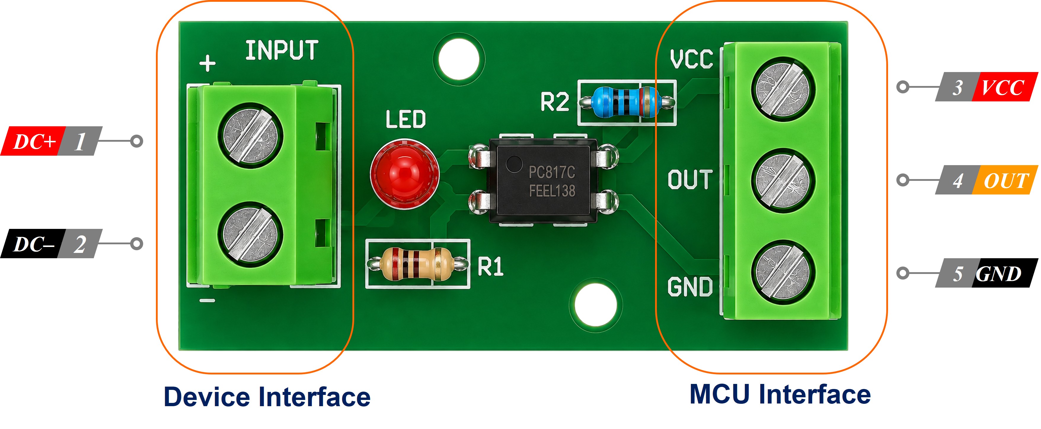
We recommend the module form for this project. The resistor is already correct for the voltage the variant was built for, the screw terminals hold thick field wiring far better than a breadboard does, and the on-board LED lets you see the input state without reading any code.
Working Out Whether Your Module Is Active LOW or Active HIGH
The ESP32 pin uses its internal pull-up resistor, so it sits HIGH on its own and something has to pull it down. On the bare chip that something is the phototransistor, and the outcome is settled physics:
- The external signal is PRESENT, the LED is on, the transistor conducts, and the ESP32 pin reads LOW.
- The external signal is ABSENT, the LED is off, the transistor is off, and the ESP32 pin reads HIGH.
A module is a different story, and this is where an evening gets lost. Some manufacturers bring the phototransistor straight out to the OUT pin, which gives exactly the active-LOW behaviour above. Others add an inverting stage on the board, so OUT follows the input instead and reads HIGH while the signal is present. Both kinds are on sale, they are indistinguishable in a product photo, and the listing rarely tells you which one is in the envelope. So do not assume - find out. The test takes under a minute:
- Wire the module up as shown below and upload the sketch from this page, which is set for an active-LOW module.
- Leave the input terminals unconnected and read what Serial Monitor prints. That is your idle state.
- Apply your signal to the input terminals and read what it prints now.
- Whatever the pin reports while the signal is present is your module's active level. If Serial Monitor swaps from idle to LIVE when you apply the signal, your module is active-LOW and the sketch is already right. If it does the opposite, your module is active-HIGH.
- The module's own status LED is the cross-check, because it lights whenever the input side is energised. LED lit but Serial Monitor still saying idle is the signature of an active-HIGH module rather than a wiring fault.
When it turns out to be the other kind, nothing gets rewritten. The sketch keeps a single constant, MODULE_ACTIVE_LOW, at the top of the file. Set it to false, upload again, and every reading in the program flips with it.
The Isolation Rule
Do NOT connect the ground of the 12V or 24V circuit to the GND of the ESP32. On a module that means the - input terminal stays on the field side and never meets the module's GND pin. The two grounds must stay separate. That separation is the entire reason the PC817 is in the circuit: it is what stops a fault on the 24V side from reaching the ESP32. If you tie the grounds together the PC817 still switches and the code still works, but the isolation is gone and the board is exposed again.
Choosing a Safe ESP32 GPIO Pin
The ESP32 is a 3.3V board and its GPIO pins are NOT 5V tolerant, so the output side of the PC817 module must be powered from the 3.3V pin, never from the 5V/VIN pin. Two more ESP32-specific rules matter for this project:
- Avoid the input-only pins GPIO34, GPIO35, GPIO36 and GPIO39. They have NO internal pull-up resistor, so INPUT_PULLUP does nothing on them and the PC817 output would float. If you really need one of these pins, you must add an external 10 kohm resistor from the pin to 3.3V yourself.
- Avoid the strapping pins GPIO0, GPIO2, GPIO12 and GPIO15. The ESP32 samples them while booting, and a PC817 pulling one of them to the wrong level at power-up can stop the board from starting.
This tutorial uses GPIO19, which is a general-purpose pin with a working internal pull-up. GPIO4, GPIO13, GPIO16, GPIO17, GPIO18, GPIO21, GPIO22, GPIO23, GPIO25, GPIO26, GPIO27, GPIO32 and GPIO33 are equally good choices. See the ESP32 pinout tutorial for the full picture.
Wiring Diagram
Wiring the PC817 optocoupler module to ESP32
The input side is the same whichever variant you bought: the two screw terminals go to the signal you are watching and to the ground of that same isolated circuit, and no resistor of your own is involved anywhere.
| PC817 module | Connects to |
|---|---|
| IN+ terminal | → the signal wire you are watching, at the voltage of your variant |
| IN- terminal | → ground of that same circuit ONLY |
| VCC pin | → 3.3V of ESP32 |
| GND pin | → GND of ESP32 |
| OUT pin | → GPIO19 of ESP32 |
The output side is where you have a choice of two ways to reach the ESP32:
- How to connect ESP32 and PC817 optocoupler module using breadboard
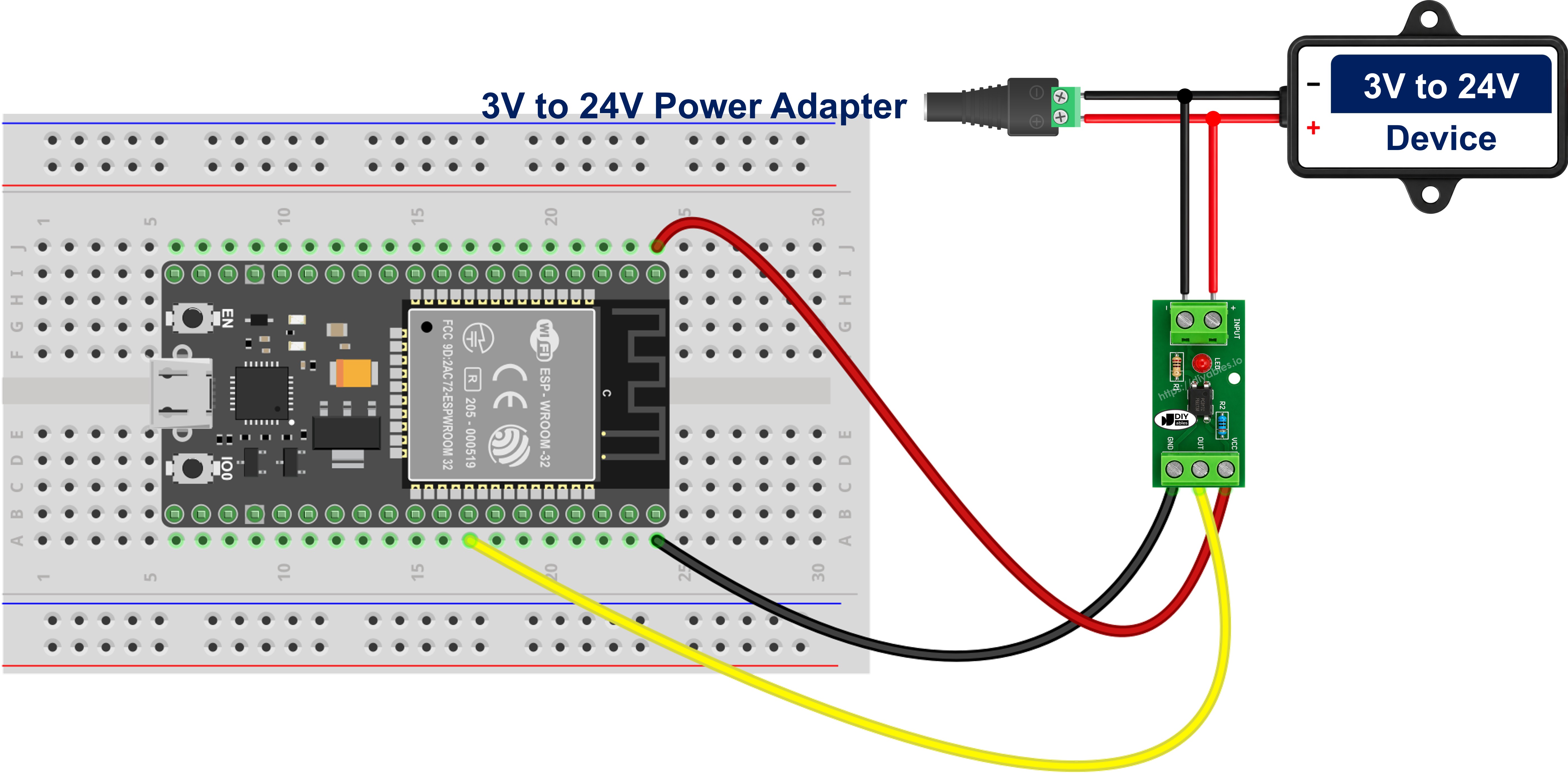
This image is created using Fritzing. Click to enlarge image
- How to connect ESP32 and PC817 optocoupler module using screw terminal block breakout board
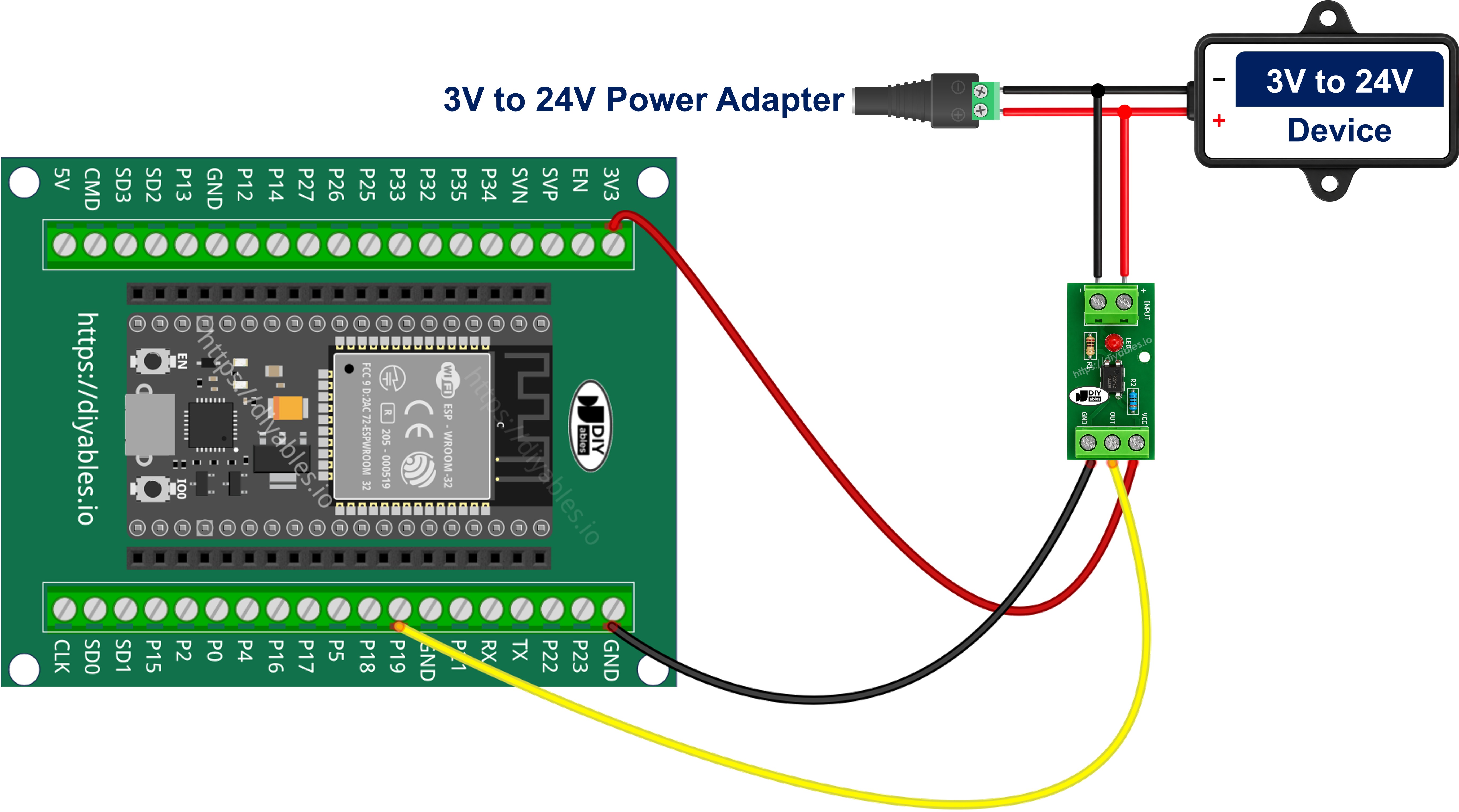
The screw terminal version is the one to use in a real installation. Field wiring from a 24V machine is thick and it moves, and a breadboard contact that shakes loose gives you a phantom reading that is very hard to debug.
Note that these two diagrams differ only in how the module's three output pins reach the ESP32. The variant you bought decides what happens on the input terminals and changes nothing on the output side, so this is two wiring choices and three variants - not six different things to buy.
Wiring the PC817 in parallel with the 12V load you want to monitor
Everything above assumes you already have a spare signal wire to read. Most real projects do not. What they have is a 12V solenoid valve, or the coil of the contactor that starts a pump, and the question is whether that coil is energised at this moment. The PC817 answers it - but only if you hang it on the circuit the right way.
The module input goes across the device, in parallel with it, and never in series with it. Put it in series and the entire load current of the valve or the contactor coil runs through the tiny LED inside the package and destroys the PC817 the instant the circuit switches on. Wired in parallel, nothing in the existing circuit is cut, unplugged or rerouted; you simply add two wires to terminals that are already there.
| Connection point | Connects to |
|---|---|
| Positive (switched) terminal of the coil | → IN+ screw terminal of the 12V module |
| Negative (return) terminal of the coil | → IN- screw terminal of the 12V module |
| Module VCC pin | → 3.3V of ESP32 |
| Module GND pin | → GND of ESP32 |
| Module OUT pin | → GPIO19 of ESP32 |
There is no series resistor to add at the tap - the 12V module already carries the one it needs, which is exactly why the variant has to match the coil's voltage. The tap draws only the small current the module's input LED needs. Next to the hundreds of milliamps a solenoid valve or a contactor coil pulls while it holds in, that is nothing, so the device carries on working exactly as it did before. This is a read-only measurement, not an intervention.
Polarity matters here. The input side of the PC817 is an LED and it conducts in one direction only, so if the two input terminals end up swapped the module simply never turns on, and you will spend an evening hunting a fault that does not exist. Work out which side of the tap is positive before you strip a wire.
A solenoid valve, a contactor coil, a relay coil or a motor is an inductive load, and an inductive load throws back a large reverse voltage every time it is switched off. The PC817 input LED is rated for only 6 V in reverse, so that spike is enough to kill it.
※ NOTE THAT:
Fit an ordinary diode in reverse-parallel directly across the module's two input terminals - diode cathode to IN+, diode anode to IN- (on the bare chip, cathode to pin 1 and anode to pin 2). In normal operation it is reverse-biased and does nothing at all; on a switch-off spike it conducts and clamps the reverse voltage to well under a volt. A 1N4148 suits a small tap, a 1N4007 a heavier one.
One more trap on the machine side: some PLC transistor outputs, triac outputs and LED-lamp drivers leak a little current even when they are switched off. Enough leakage partially lights the PC817 LED, and the ESP32 then reports the valve as running while it is sitting idle. The symptom is easy to recognise - a reading that never falls back to inactive. The cure is a bleeder resistor of about 4.7 kohm to 10 kohm fitted in parallel with the module input terminals, so the leakage drains through it instead of through the LED.
Finally, this is a DC-only technique. The PC817 input is a single LED and responds to one polarity, so it is the wrong part for sensing an AC line - that job needs an optocoupler whose input stage carries two back-to-back LEDs.
If you're unfamiliar with how to supply power to the ESP32 and other components, you can find guidance in the following tutorial: The best way to Power ESP32 and sensors/displays.
Optional - Building the Same Input From a Bare PC817 Chip
If you would rather build the input yourself than buy a module, the bare 4-pin chip does the same job - you just supply the resistor the module would have had fitted. Hold the chip so the dot or notch marking pin 1 is at the top-left; the pins run counter-clockwise from there. Connect this pin 1 (Anode) to the signal wire through the series resistor, connect this pin 2 (Cathode) to the ground of the isolated circuit and nowhere else, connect this pin 3 (Emitter) to a GND pin of the ESP32, and connect this pin 4 (Collector) to GPIO19. Size the resistor for about 10 mA through the LED with R = (Vin - 1.2) / 0.01, which gives 220 ohm for a 3.3V signal, 390 ohm for 5V, 1 kohm for 12V and 2.2 kohm for 24V. Never carry the 12V resistor over to a 24V line: 1 kohm there pushes about 22.8 mA through an LED rated for 20 mA. Wired this way the bare chip is always active-LOW, so the sketch needs no change.
What the Reading Tells You About the Running Device
Because the tap sits in parallel with the valve or the contactor coil rather than in the command wire, what the ESP32 reads is the real state of the device, not an echo of the order you gave it. If a pressure switch, a timer, a PLC or a person on the shop floor switches the pump on, the reading follows. If you commanded it on and it never came on - a blown fuse, a tripped overload, a broken wire out in the field - the reading stays inactive and says so. That is what turns this small circuit into a run-hour counter for a pump, a "did the valve actually open?" alert, or an idle-time log for a machine, all of it reported over WiFi and none of it sharing a wire with the 12V side.
Be honest about what the reading proves, though: it tells you the device is energised, not that it is doing its job - a seized pump motor or a burnt-out heater element still draws power and will still read as ON.
How To Program ESP32 to Read the PC817
- Configure the ESP32 pin as a digital input with the internal pull-up resistor enabled by using the pinMode() function. The pull-up is what makes the idle state HIGH. For example, pin GPIO19:
- Read the raw state of the pin by using the digitalRead() function.
- Turn that raw level into a signal state in a single line, through the polarity constant, so the rest of the code reads naturally and a module of the other kind costs you one edit rather than a rewrite.
- Print the result by using Serial.println(), or use it to drive anything else - for example a relay.
ESP32 Code - PC817 Optocoupler
Quick Instructions
- If this is the first time you use ESP32, see how to setup environment for ESP32 on Arduino IDE.
- Do the wiring as the module wiring diagram above, and double-check that the 12V/24V ground is NOT touching the ESP32 GND.
- Connect the ESP32 board to your PC via a USB cable.
- Open Arduino IDE on your PC.
- Select the right ESP32 board (e.g. ESP32 Dev Module) and COM port.
- Copy the above code and paste it to Arduino IDE.
- Click to the Upload button on Arduino IDE to compile and upload the code to the ESP32 board.
- Open Serial Monitor on Arduino IDE.
- Switch the external 12V or 24V signal on and off a few times.
- Compare what Serial Monitor says against the module's status LED. If the two disagree, set MODULE_ACTIVE_LOW to false in the code and upload again.
- See the result on Serial Monitor. It looks like the below:
If Serial Monitor keeps printing LIVE while nothing is connected, one of two things is happening. Either the ESP32 pin is floating - check that you picked a pin that actually has an internal pull-up, and that the module GND (or pin 3 of the bare chip) really reaches an ESP32 GND pin - or your module is an active-HIGH one, which the status LED will tell you in a second.
If you want to go further with digital inputs on this board, the ESP32 - Button and ESP32 - Limit Switch tutorials cover the same read-and-invert pattern for mechanical contacts, and ESP32 - Measure Voltage covers the case where you need the actual voltage value rather than just present/absent.
Video Tutorial
Making video is a time-consuming work. If the video tutorial is necessary for your learning, please let us know by subscribing to our YouTube channel , If the demand for video is high, we will make the video tutorial.