
ESP32 - IR Slotted Optical Speed Sensor
This tutorial instructs you how to use ESP32 to read the state of an IR slotted optical speed sensor, count the objects that pass through its slot, and turn the pulses from an encoder disc into a motor speed in RPM that is printed to Serial Monitor.
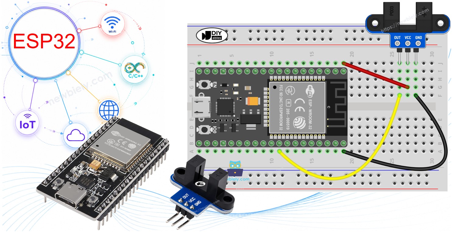
This tutorial shows how to program the ESP32 using the Arduino language (C/C++) via the Arduino IDE. If you’d like to learn how to program the ESP32 with MicroPython, visit this ESP32 MicroPython - IR Slotted Optical Speed Sensor tutorial.
Hardware Used In This Tutorial
Or you can buy the following kits:
| 1 | × | DIYables ESP32 Starter Kit (ESP32 included) | |
| 1 | × | DIYables ESP32 S3 Starter Kit (ESP32 S3 included) | |
| 1 | × | DIYables Sensor Kit (18 sensors/displays) |
Introduction to IR Slotted Optical Speed Sensor
This small module has a U shape with a narrow gap in the middle. People call it by many names: photo interrupter, opto interrupter, U-shaped IR sensor or simply slot sensor. It does one job. It tells the ESP32 whether something is sitting inside the gap or not. Because it can switch very fast, it is a good choice for measuring how fast a wheel or a motor turns.
| IR Slotted Optical Speed Sensor | |
|---|---|
| The sensor type | slot-type photoelectric (IR LED + NPN phototransistor) |
| The slot width | 5.9 mm |
| The output | digital (TTL), LOW when blocked, HIGH when clear |
| The signal conditioning | built-in Schmitt trigger |
| The mounting | M3 screw holes at both ends |
| The number of pins | 3 (VCC, GND, OUT) |
| Operating Voltage | 3.3V to 5V DC |
Typical uses are motor speed (RPM) measurement with an encoder disc, a simple tachometer, counting objects or pulses, measuring distance by counting wheel turns, wheel speed feedback for a robot car, and limit or position detection.
IR Slotted Optical Speed Sensor Pinout
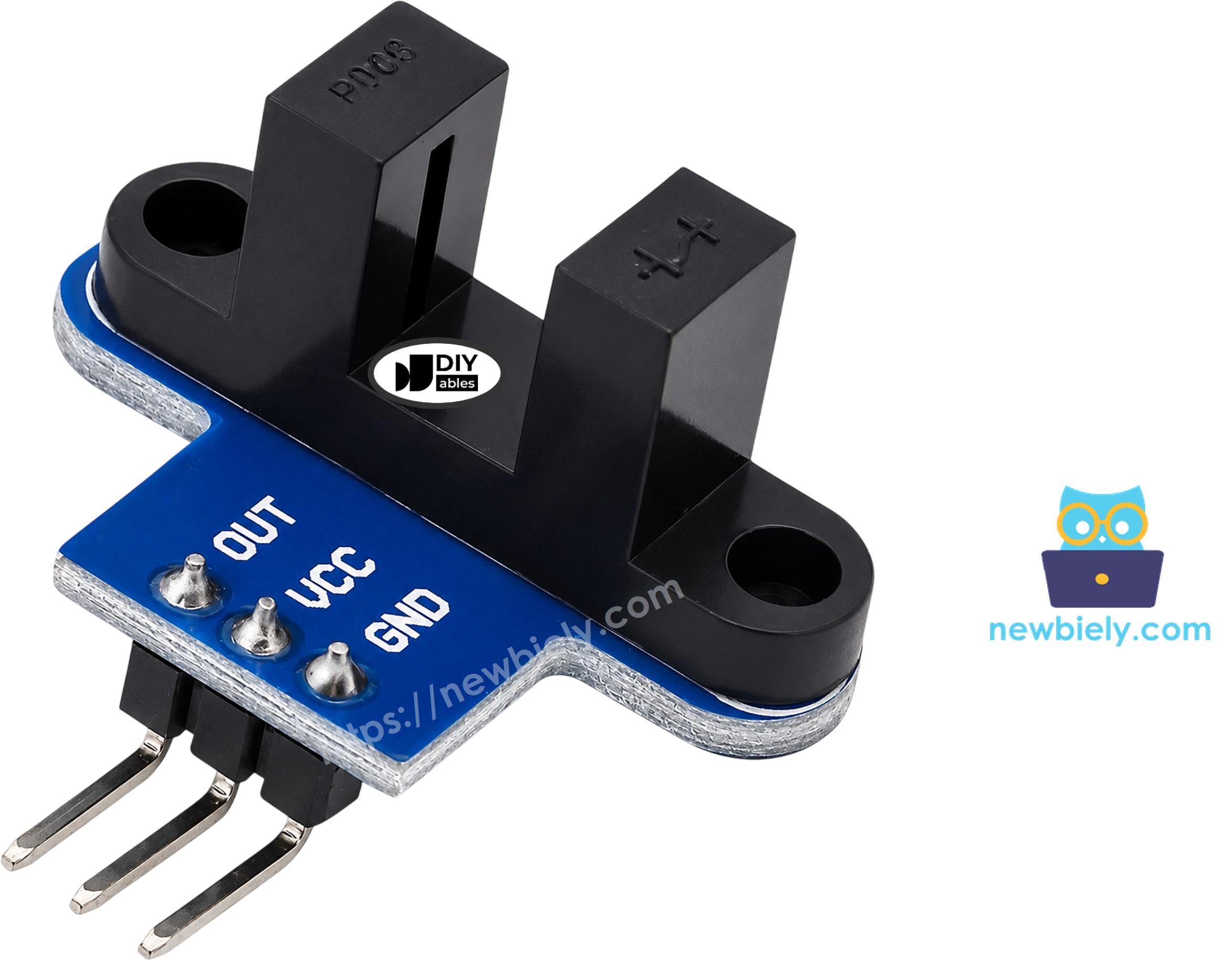
- VCC pin: connect this pin to the 3.3V pin of the ESP32
- GND pin: connect this pin to GND (0V)
- OUT pin: connect this pin to an input pin of the ESP32 (GPIO18 in this tutorial). It gives LOW when the slot is blocked and HIGH when it is clear
The pin order is not always the same from one batch to another. Read the labels printed on your own module before you connect the wires.
The OUT pin goes as high as the voltage you give to VCC. The ESP32 is a 3.3V board, so power the sensor from the 3.3V pin, not from 5V. In this way, the OUT pin never sends more than 3.3V into the GPIO pin.
How IR Slotted Optical Speed Sensor Works

One arm of the U holds an infrared LED. The other arm holds an NPN phototransistor. The two face each other across the 5.9 mm gap.
- Nothing in the gap: the IR light reaches the phototransistor, and the OUT pin is HIGH.
- An opaque object in the gap, such as a piece of card or one tooth of an encoder disc: the light is cut, and the OUT pin is LOW.
A Schmitt trigger on the board turns the raw light level into a clean 0 or 1 with no shaking between the two. Thanks to it, the ESP32 code does not need any debounce.
Clear plastic may let the IR light pass, so it is not always seen as blocked. Use objects that you cannot see through.
Some modules from other makers work the other way around. If your sensor says "blocked" when the gap is empty, just swap LOW and HIGH in the first code. The RPM code counts one edge for each slot of the disc, so it works with both types.
Wiring Diagram
How to connect ESP32 and IR slotted optical speed sensor
Only three wires are needed. Connect VCC to 3.3V, GND to GND, and OUT to GPIO18. You can plug the wires straight into the pins, or use a breadboard if you like.
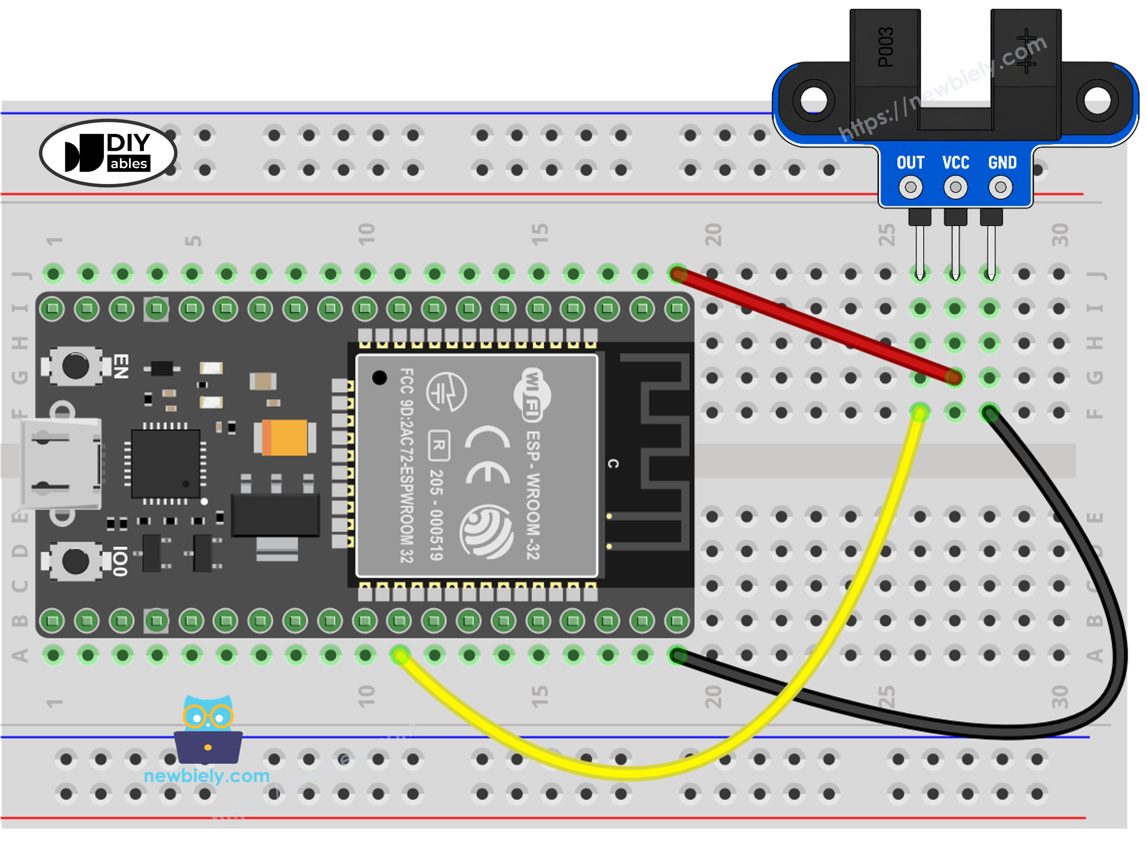
This image is created using Fritzing. Click to enlarge image
| IR Slotted Optical Speed Sensor | ESP32 |
|---|---|
| VCC | 3.3V |
| GND | GND |
| OUT | GPIO18 |
How to set up the encoder disc for speed measurement
To measure speed, the sensor needs something that cuts the light again and again while it turns. That is the job of the encoder disc. Fix the disc on the motor shaft or the wheel, then fix the sensor with its M3 holes so the teeth of the disc pass through the gap. The disc must not touch the sensor at any point of the turn.
You can spin the disc by hand for a first test. To spin it with a motor, see the ESP32 DC motor tutorial, because the motor needs its own wiring.
If you're unfamiliar with how to supply power to the ESP32 and other components, you can find guidance in the following tutorial: The best way to Power ESP32 and sensors/displays.
How To Program For IR Slotted Optical Speed Sensor
No library is needed. The two examples below use only functions that come with the ESP32 core.
- Set the pin as an input: pinMode(SENSOR_PIN, INPUT);
- Read the state of the slot (LOW means blocked): int state = digitalRead(SENSOR_PIN);
- Do something only when the state changes: if (state != lastState) { ... }
- Call a short function every time a tooth blocks the slot: attachInterrupt(digitalPinToInterrupt(SENSOR_PIN), countPulse, FALLING);
- Mark that function with IRAM_ATTR so the ESP32 can run it fast: void IRAM_ATTR countPulse() { pulseCount++; }
- Turn the pulses of one second into turns per minute: float rpm = pulses * 60.0 / SLOTS_PER_TURN;
Why use an interrupt for speed? When the motor runs fast, the pulses come very close to each other, and a simple check inside loop() can miss some of them. The interrupt catches every one. The FALLING edge is chosen so that each tooth is counted only once. To learn more, read the ESP32 GPIO interrupt tutorial.
ESP32 Code - Detect and Count Objects in the Slot
This code checks the OUT pin again and again. It prints a message only when the state changes. Each time the slot becomes blocked, the counter goes up by one.
Quick Instructions
If this is the first time you use ESP32, see how to setup environment for ESP32 on Arduino IDE.
- Connect the sensor to the ESP32 as shown in the wiring diagram.
- Plug the USB cable into the ESP32 and your PC.
- Open Arduino IDE, then select the ESP32 Dev Module board and the right COM port.
- Copy the above code and paste it into Arduino IDE.
- Click to the Upload button on Arduino IDE to compile and upload the code to the ESP32.
- Click to the Serial Monitor icon, then type or select 9600 as the baud rate.
- Move a piece of card or your finger into the slot, then take it out. Do it a few times.
- Look at the messages on Serial Monitor.
ESP32 Code - Measure Motor Speed (RPM)
Now the sensor works as a tachometer. Every tooth of the disc that blocks the slot starts the interrupt, which adds one to a counter. Once per second, the code reads the counter, sets it back to zero, and works out the speed.
The math is simple. A common encoder disc, like the one sold with TT gear motors, has 20 slots, so one full turn gives 20 pulses. The pulses in one second, times 60, gives the pulses in one minute. Divide that by 20 and you get the turns per minute (RPM). If your disc has a different number of slots, change the value of SLOTS_PER_TURN in the code.
Quick Instructions
- Fix the encoder disc and the sensor as shown in the encoder disc picture above. The wiring to the ESP32 stays the same.
- Copy the above code, paste it into Arduino IDE and click to the Upload button.
- Open Serial Monitor at 9600 baud.
- Spin the disc by hand, or power the motor.
- Watch the speed on Serial Monitor. The example below is a motor turning at around 300 RPM, with the motor stopped at the start and at the end.
Do you also want to know how far a wheel has gone? Multiply the number of turns by the wheel circumference (π × wheel diameter).
If you want to detect an object a few centimeters away instead of inside a slot, see the ESP32 infrared obstacle avoidance sensor tutorial. If you need a knob that also gives the turning direction, see the ESP32 rotary encoder tutorial.
Video Tutorial
Making video is a time-consuming work. If the video tutorial is necessary for your learning, please let us know by subscribing to our YouTube channel , If the demand for video is high, we will make the video tutorial.