
ESP32 - MAX6675 Thermocouple Module
Most of the temperature sensors we cover in other tutorials - the DS18B20, DHT22, LM35, and the like - top out somewhere around 100-150°C. That is plenty for a room, a fridge, or a garden bed, but it is useless if you need to know how hot a furnace, a soldering iron tip, or the inside of a pizza oven really gets. For jobs like that, hobbyists reach for a thermocouple instead, paired with a small digitizer chip called the MAX6675.
In this tutorial we will hook up an ESP32 to a MAX6675 breakout board and a Type-K thermocouple probe, then read out the temperature on the Serial Monitor in both Celsius and Fahrenheit.
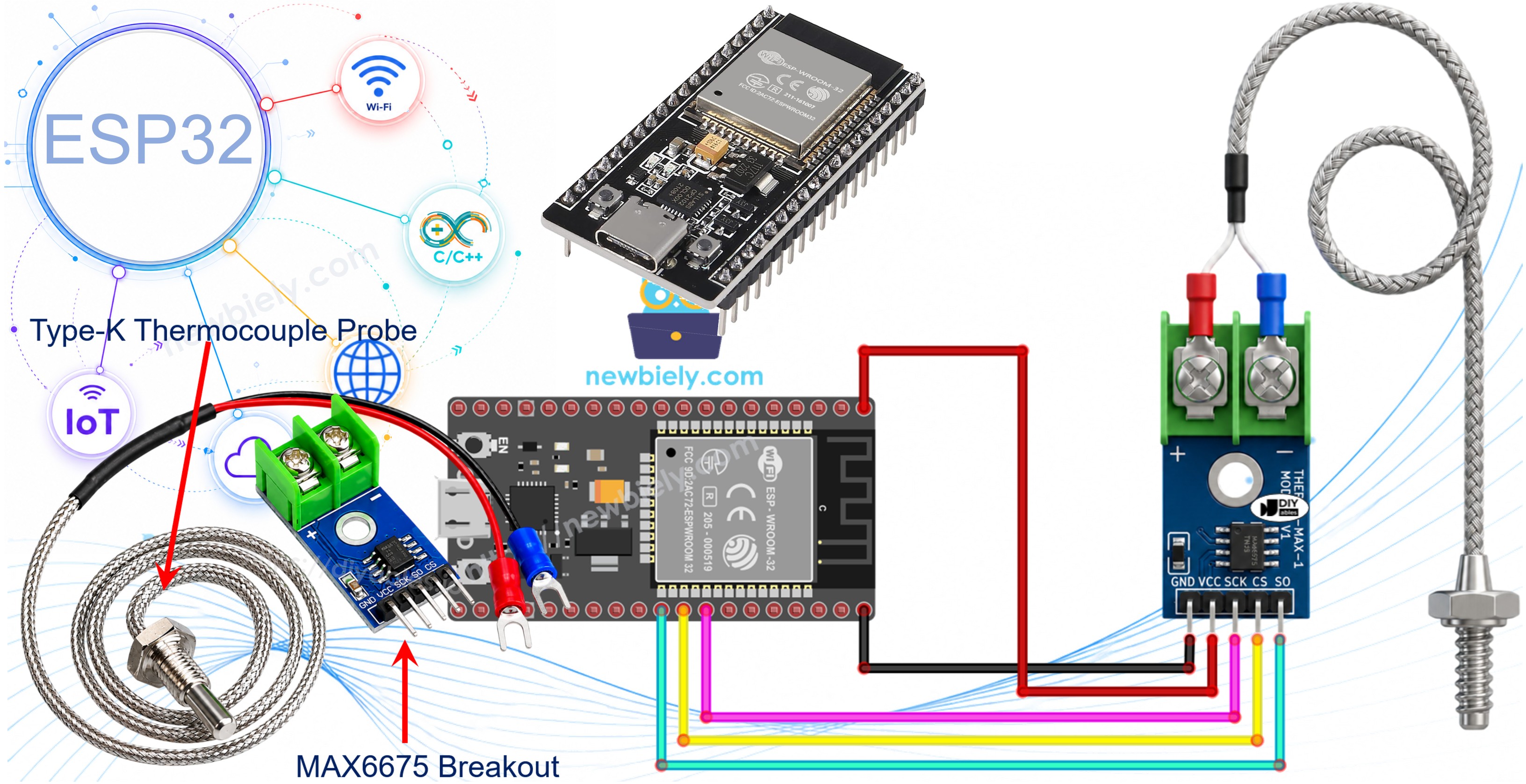
Hardware Used In This Tutorial
Or you can buy the following kits:
| 1 | × | DIYables ESP32 Starter Kit (ESP32 included) | |
| 1 | × | DIYables ESP32 S3 Starter Kit (ESP32 S3 included) | |
| 1 | × | DIYables Sensor Kit (18 sensors/displays) |
What Exactly Is a Thermocouple?
A thermocouple is simply two different metal wires welded together at one end, forming what's called the hot junction. Once that junction gets hot (or cold), a tiny voltage appears across the wires, and that voltage rises and falls with the temperature. Because it is just two bits of wire rather than a delicate silicon sensor, a thermocouple can survive - and measure - places that would instantly kill a normal sensor. The Type-K version, made from Chromel and Alumel wire, is by far the most common and can handle roughly -328°F to +2300°F.
Introduction to the MAX6675 Module
On its own, the millivolt-level signal from a thermocouple is too small and too messy for a microcontroller to read directly. The MAX6675 module solves that: it is a small breakout board built around the MAX6675 IC, sold together with a Type-K probe already wired to it.
MAX6675 Module Pinout
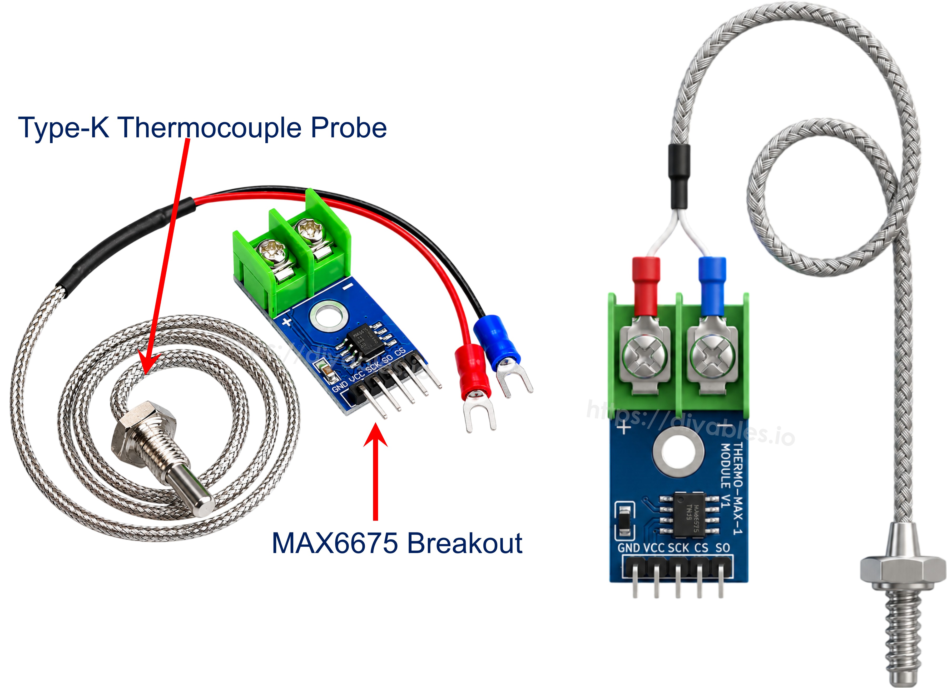
The MAX6675 chip on the breakout continuously samples the probe's signal, cold-junction compensates it internally, and hands the ESP32 a ready-to-use 12-bit temperature reading over a simple 3-wire bus. Its pins are:
- VCC: power input, 3.0V to 5.5V.
- GND: ground.
- SCK: serial clock input, driven by the ESP32.
- CS: chip select - the ESP32 pulls this low while it is reading a sample.
- SO: serial data output only (there is no data-in pin; the module never receives commands, it only talks).
A small screw-terminal block on the opposite edge of the board is where the probe plugs in, marked + and -; the probe's red lead goes to + and the blue lead to -.
Rounding out the specs: the breakout itself can digitize temperatures from 0°C up to 1024°C, holds about ±3°C of accuracy, and resolves readings down to roughly 0.25°C - although the bundled probe, described next, is the real limiting factor.
The Bundled Type-K Probe
The probe that ships with the module is a thin stainless-steel-tipped cable, around 18 inches long, and it is only rated from 0°C to 80°C - fine for a cup of coffee or a terrarium, but you'd want a higher-rated probe before pointing this at a kiln. Look for the red (positive) and blue (negative) wires at the end that plugs into the breakout's terminal block.
Wiring Diagram
Power the module from the ESP32: VCC to 5V (3.3V also works) and GND to GND. The remaining three pins - SCK, CS, and SO - each go to any spare GPIO on the ESP32, since the library drives them with simple bit-banging rather than the hardware SPI peripheral. Last, seat the thermocouple probe's red and blue leads into the module's + and - terminals.
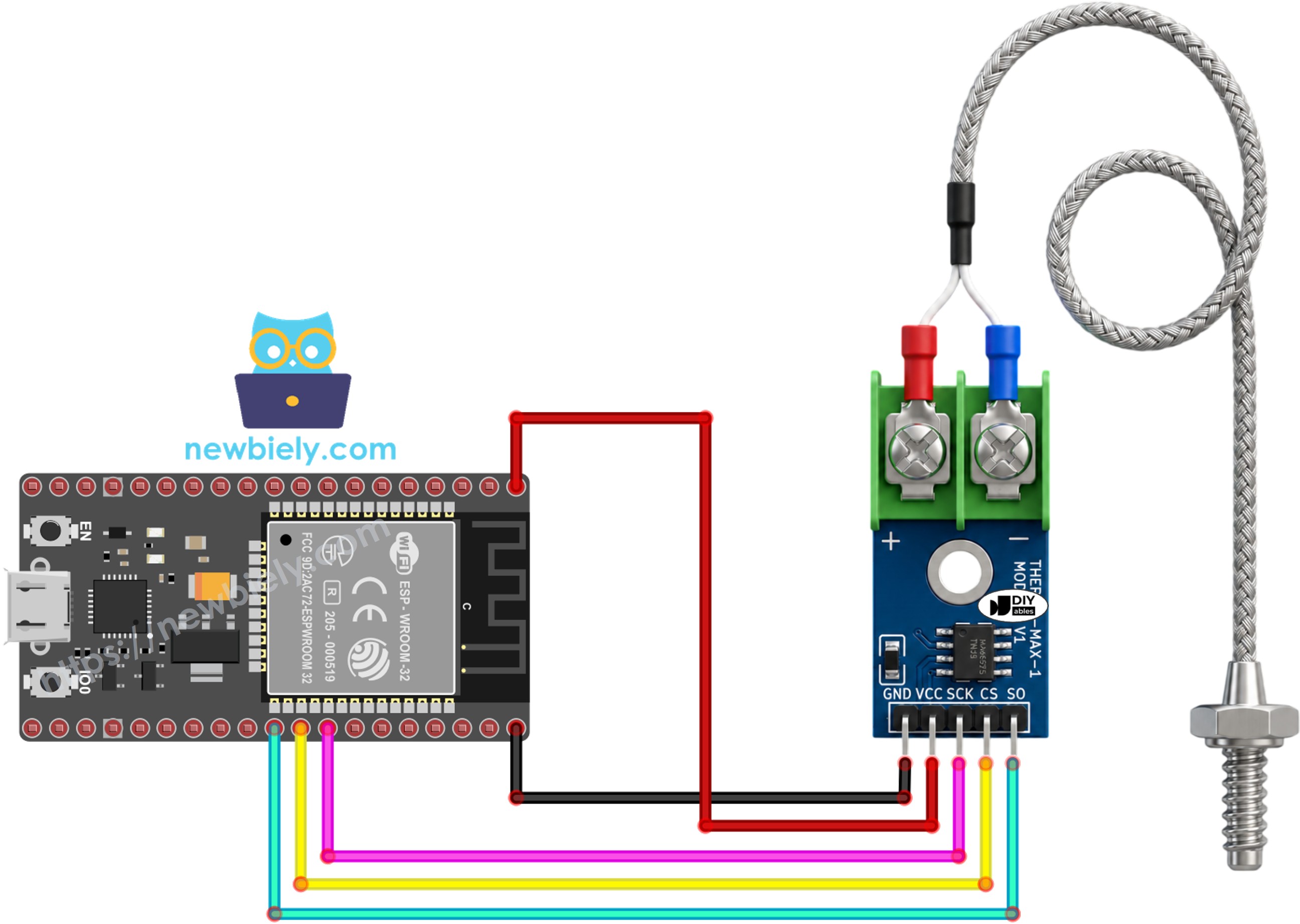
This image is created using Fritzing. Click to enlarge image
Wiring table between MAX6675 Module and ESP32
| MAX6675 Module | ESP32 |
|---|---|
| VCC | → 5V |
| GND | → GND |
| SCK | → GPIO19 |
| CS | → GPIO18 |
| SO | → GPIO5 |
If you're unfamiliar with how to supply power to the ESP32 and other components, you can find guidance in the following tutorial: The best way to Power ESP32 and sensors/displays.
ESP32 Code
Quick Instructions
- New to ESP32? Start with setting up the ESP32 environment in the Arduino IDE first.
- Wire the MAX6675 module and thermocouple probe to the ESP32 as shown in the diagram above.
- Plug the ESP32 into your computer with a USB cable.
- Open the Arduino IDE.
- Under Tools, pick the matching ESP32 board (e.g. ESP32 Dev Module) and the correct COM port.
- Open the Libraries panel from the left-hand icon bar.
- Type "MAX6675" into the search box and find the library published by Adafruit.
- Press Install.
- Search for MAX6675 library created by Adafruit and click the Install button.
- Paste the code above into the IDE.
- Hit Upload to flash the sketch onto the ESP32.
- Warm the thermocouple tip up (hold it, breathe on it, dip it in warm water) or let it cool down.
- Open the Serial Monitor to watch the readings roll in.
※ NOTE THAT:
Seeing a frozen or clearly wrong reading? Re-check the SCK/CS/SO wiring first, then confirm the thermocouple's red and blue leads are seated firmly in the module's screw terminals - a loose lead is the most common cause of a stuck or nonsensical reading.
Code Explanation
The sketch starts by pulling in the MAX6675 library header, which gives the ESP32 sketch access to the MAX6675 class.
Three constants record which ESP32 GPIOs the module's SCK, CS, and SO pins are wired to.
A single MAX6675 object, thermocouple, is then constructed with those three pins - this is what the rest of the sketch will call to take a reading.
setup() only needs to bring up the serial port so we have somewhere to print the results, plus a brief delay to let the MAX6675 finish powering up before the first read.
Inside loop(), the two library calls that matter are:
- Thermocouple.readCelsius(): fetches the latest reading in degrees Celsius.
- Thermocouple.readFahrenheit(): fetches the same reading converted to Fahrenheit.
A one-second delay() closes out the loop so the readings scroll by at a comfortable pace instead of flooding the Serial Monitor.
Video Tutorial
Making video is a time-consuming work. If the video tutorial is necessary for your learning, please let us know by subscribing to our YouTube channel , If the demand for video is high, we will make the video tutorial.