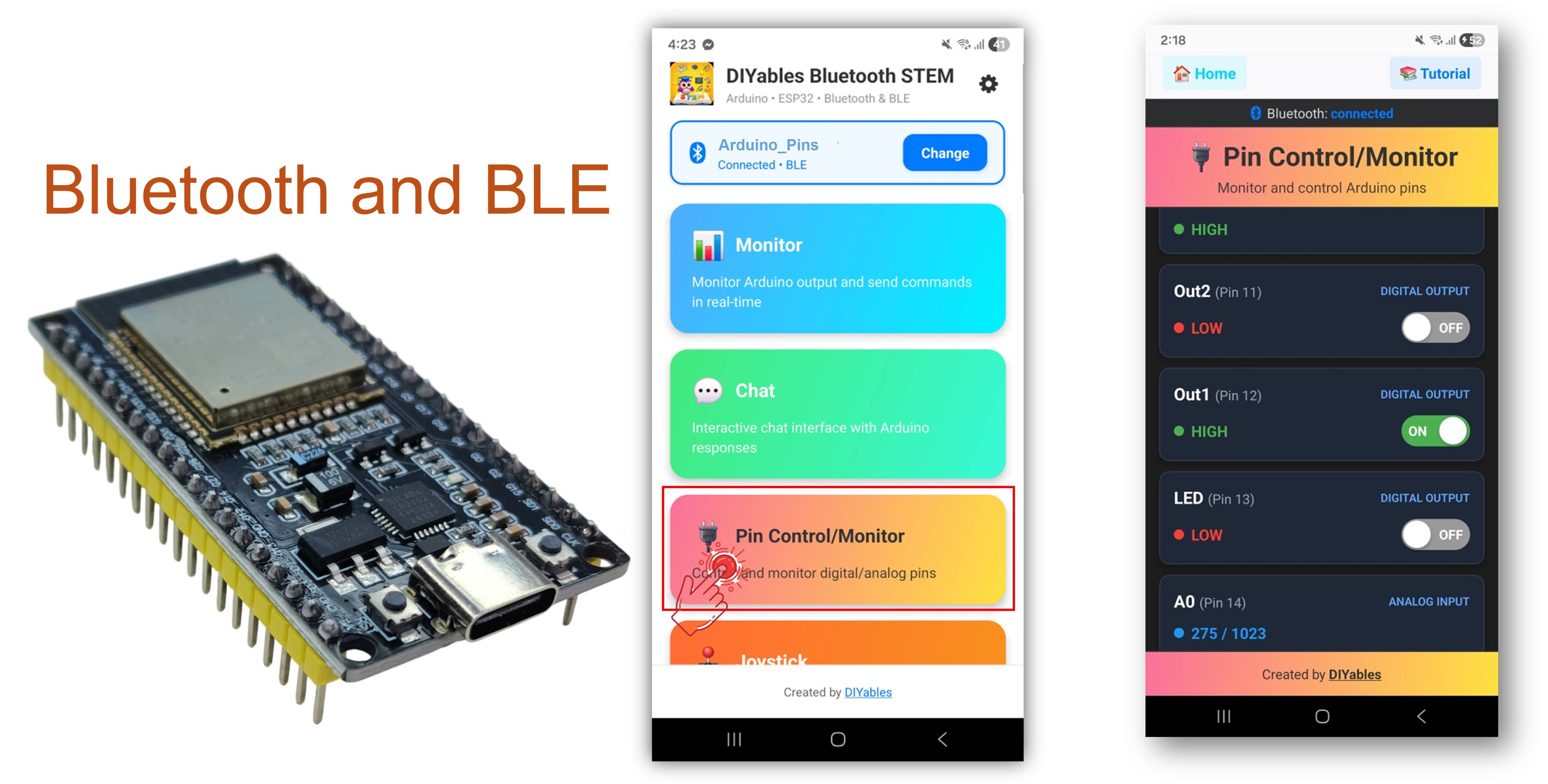
The Bluetooth Digital Pins example provides remote control and monitoring of ESP32 GPIO pins through the DIYables Bluetooth STEM app. Designed for ESP32 boards with support for both BLE (Bluetooth Low Energy) and Classic Bluetooth connections. Configure pins as inputs or outputs, toggle output pins, read digital and analog input states, and receive real-time pin change notifications — perfect for home automation, relay control, button monitoring, and sensor reading.
This example supports two Bluetooth modes:
ESP32 BLE (Bluetooth Low Energy): Works on both Android and iOS
ESP32 Classic Bluetooth: Works on Android only. iOS does not support Classic Bluetooth. Use BLE if you need iOS support.
Features
Output Pin Control: Toggle digital output pins HIGH/LOW from the app
Input Pin Monitoring: Read digital and analog input pin states
Custom Pin Names: Assign friendly names to each pin (e.g., "LED", "Btn1", "A34")
Real-Time Updates: Automatic notifications when input pin states change
Up to 16 Pins: Support for up to 16 configurable pins simultaneously
Mixed Modes: Combine input and output pins in the same setup
BLE & Classic Bluetooth: Choose the Bluetooth mode that suits your project
Cross-Platform: BLE mode works on both Android and iOS; Classic Bluetooth works on Android
Disclosure: Some of the links in this section are Amazon affiliate links, meaning we may earn a commission at no additional cost to you if you make a purchase through them. Additionally, some links direct you to products from our own brand, DIYables .
Connect the ESP32 board to your computer using a USB cable.
Launch the Arduino IDE on your computer.
Select the appropriate ESP32 board and COM port.
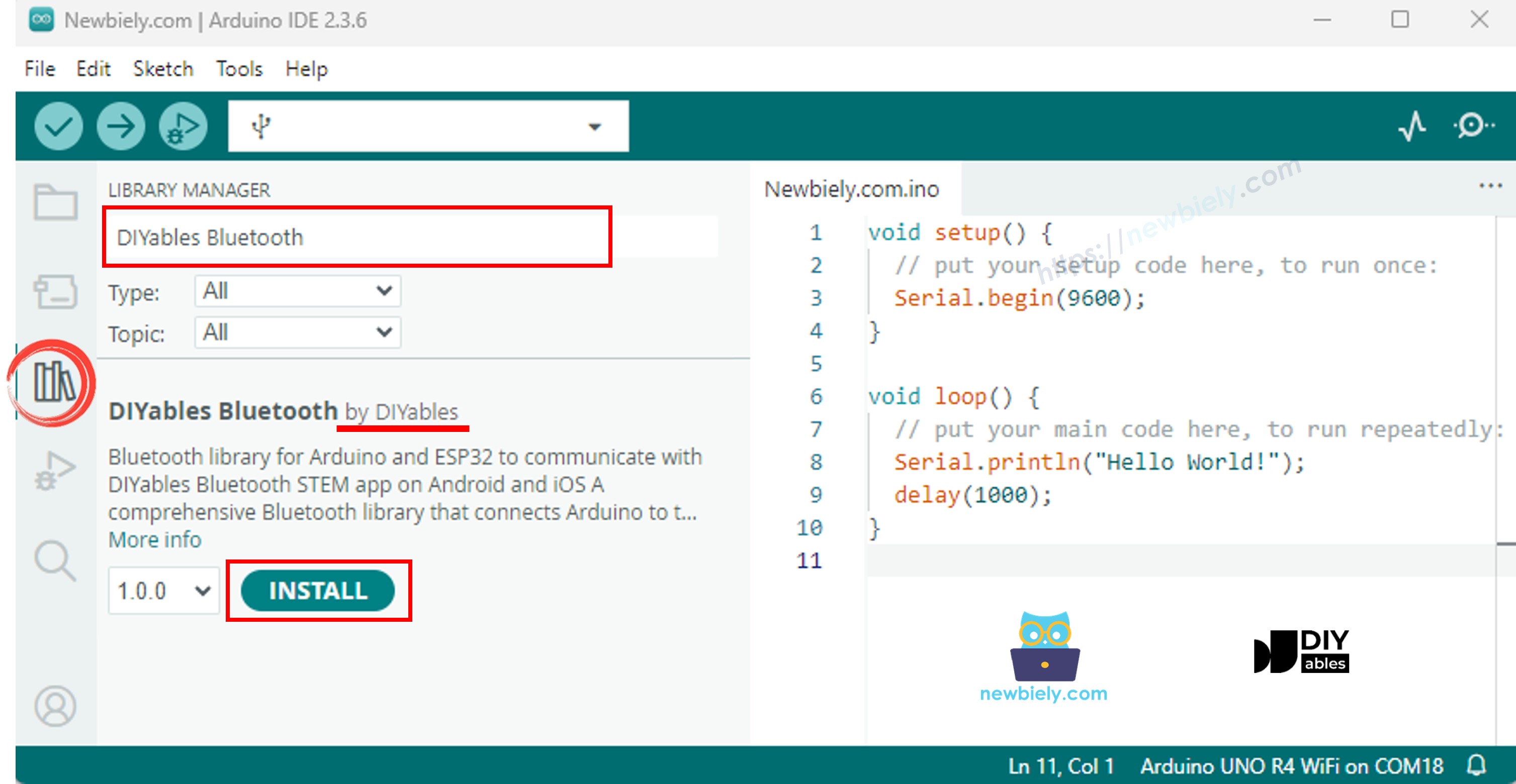
Navigate to the Libraries icon on the left bar of the Arduino IDE.
Search "DIYables Bluetooth", then find the DIYables Bluetooth library by DIYables
Click Install button to install the library.
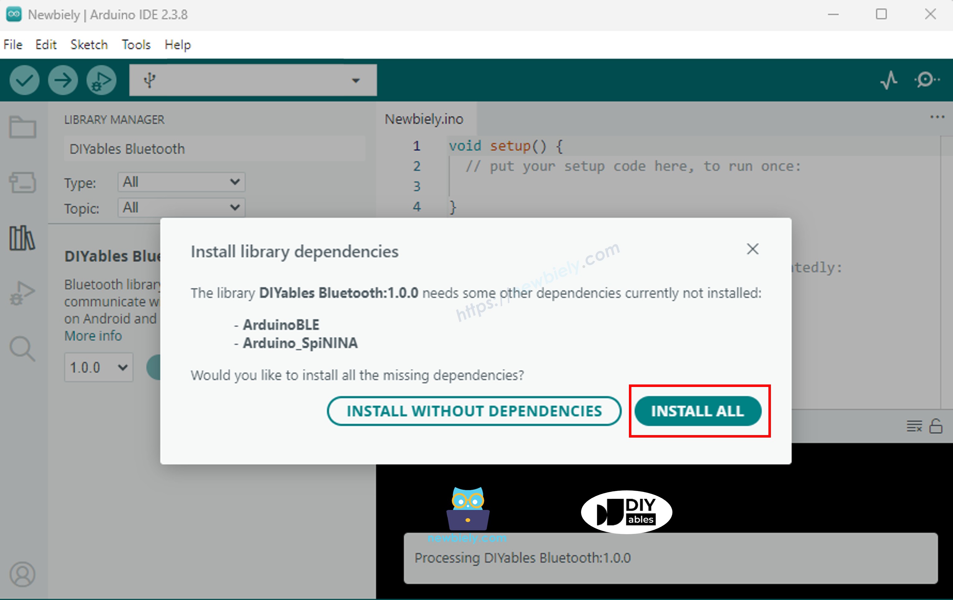
You will be asked for installing some other library dependencies
Click Install All button to install all library dependencies.
Choose one of the two Bluetooth modes below depending on your needs:
ESP32 Classic Bluetooth Code (works with app on Android only)
Note: Classic Bluetooth is NOT supported on iOS. If you need iOS support, use the BLE code below.
On Arduino IDE, Go to File Examples DIYables Bluetooth Esp32Bluetooth_PinControl example, or copy the above code and paste it to the editor of Arduino IDE
/* * DIYables Bluetooth Library - ESP32 Classic Bluetooth Pin Control Example * Works with DIYables Bluetooth STEM app on Android * Note: Classic Bluetooth is NOT supported on iOS. Use BLE examples for iOS support. * * This example demonstrates the Bluetooth Pin Control/Monitor feature: * - Control digital output pins via Bluetooth * - Monitor digital input pins * - Monitor analog input pins * - Configure pin modes (INPUT/OUTPUT) * * Compatible Boards: * - ESP32 (all variants with Classic Bluetooth) * - ESP32-WROOM-32 * - ESP32-DevKitC * - ESP32-WROVER * * Note: Select "Huge APP (3MB No OTA/1MB SPIFFS)" partition scheme * in Arduino IDE: Tools > Partition Scheme * * Setup: * 1. Upload the sketch to your ESP32 * 2. Open Serial Monitor (115200 baud) to see connection status * 3. Use DIYables Bluetooth App to connect and control pins * * Tutorial: https://diyables.io/bluetooth-app * Author: DIYables */#include <DIYables_BluetoothServer.h>#include <DIYables_BluetoothPinControl.h>#include <platforms/DIYables_Esp32Bluetooth.h>// Create Bluetooth instancesDIYables_Esp32Bluetooth bluetooth("ESP32_Pins");DIYables_BluetoothServer bluetoothServer(bluetooth);// Create Pin Control/Monitor app instanceDIYables_BluetoothPinControl bluetoothPins;// Pin configuration (adjust for your ESP32 board)constint LED_PIN = 2; // Built-in LED on most ESP32 boardsconstint OUTPUT_PIN_1 = 16;constint OUTPUT_PIN_2 = 17;constint INPUT_PIN_1 = 18;constint INPUT_PIN_2 = 19;constint ANALOG_PIN_1 = 34; // ESP32 ADC1 pins (input only)constint ANALOG_PIN_2 = 35;voidsetup() {Serial.begin(115200);delay(1000);Serial.println("DIYables Bluetooth - ESP32 Pin Control/Monitor Example");// Initialize pinspinMode(LED_PIN, OUTPUT);pinMode(OUTPUT_PIN_1, OUTPUT);pinMode(OUTPUT_PIN_2, OUTPUT);pinMode(INPUT_PIN_1, INPUT_PULLUP);pinMode(INPUT_PIN_2, INPUT_PULLUP);// Initialize Bluetooth server with platform-specific implementation bluetoothServer.begin();// Add digital pins app to server bluetoothServer.addApp(&bluetoothPins);// Configure which pins are accessible via Bluetooth with custom names bluetoothPins.enablePin(LED_PIN, BT_PIN_OUTPUT, "LED"); bluetoothPins.enablePin(OUTPUT_PIN_1, BT_PIN_OUTPUT, "Out1"); bluetoothPins.enablePin(OUTPUT_PIN_2, BT_PIN_OUTPUT, "Out2"); bluetoothPins.enablePin(INPUT_PIN_1, BT_PIN_INPUT, "Btn1"); bluetoothPins.enablePin(INPUT_PIN_2, BT_PIN_INPUT, "Btn2"); bluetoothPins.enablePin(ANALOG_PIN_1, BT_PIN_INPUT, "A34"); bluetoothPins.enablePin(ANALOG_PIN_2, BT_PIN_INPUT, "A35");// Set up connection event callbacks bluetoothServer.setOnConnected([]() {Serial.println("Bluetooth connected!"); }); bluetoothServer.setOnDisconnected([]() {Serial.println("Bluetooth disconnected!"); });// Set up callback for pin write commands bluetoothPins.onPinWrite([](int pin, int state) {digitalWrite(pin, state);Serial.print("Pin ");Serial.print(pin);Serial.print(" set to ");Serial.println(state ? "HIGH" : "LOW"); });// Set up callback for pin read commands bluetoothPins.onPinRead([](int pin) -> int {// Read analog pins with analogRead, digital pins with digitalReadint state;if (pin == ANALOG_PIN_1 || pin == ANALOG_PIN_2) { state = analogRead(pin);Serial.print("Analog pin ");Serial.print(pin);Serial.print(" read: ");Serial.println(state); } else { state = digitalRead(pin);Serial.print("Digital pin ");Serial.print(pin);Serial.print(" read: ");Serial.println(state ? "HIGH" : "LOW"); }return state; });// Set up callback for pin mode changes bluetoothPins.onPinModeChange([](int pin, int mode) {pinMode(pin, mode == BT_PIN_OUTPUT ? OUTPUT : INPUT_PULLUP);Serial.print("Pin ");Serial.print(pin);Serial.print(" mode changed to ");Serial.println(mode == BT_PIN_OUTPUT ? "OUTPUT" : "INPUT"); });Serial.println("Waiting for Bluetooth connection...");Serial.print("Enabled pins: ");Serial.println(bluetoothPins.getEnabledPinCount());}voidloop() {// Handle Bluetooth server communications bluetoothServer.loop();// Optional: Monitor input pins and send updatesstaticunsignedlong lastInputCheck = 0;staticint lastInputState1 = HIGH;staticint lastInputState2 = HIGH;staticint lastAnalogState1 = 0;staticint lastAnalogState2 = 0;if (millis() - lastInputCheck >= 100) { lastInputCheck = millis();// Check digital input pin 1int currentState1 = digitalRead(INPUT_PIN_1);if (currentState1 != lastInputState1) { lastInputState1 = currentState1; bluetoothPins.updatePinState(INPUT_PIN_1, currentState1);Serial.print("Input pin ");Serial.print(INPUT_PIN_1);Serial.print(" changed to ");Serial.println(currentState1 ? "HIGH" : "LOW"); }// Check digital input pin 2int currentState2 = digitalRead(INPUT_PIN_2);if (currentState2 != lastInputState2) { lastInputState2 = currentState2; bluetoothPins.updatePinState(INPUT_PIN_2, currentState2);Serial.print("Input pin ");Serial.print(INPUT_PIN_2);Serial.print(" changed to ");Serial.println(currentState2 ? "HIGH" : "LOW"); }// Check analog input 1 (send update if changed by more than 50 - ESP32 has 12-bit ADC)int currentAnalog1 = analogRead(ANALOG_PIN_1);if (abs(currentAnalog1 - lastAnalogState1) > 50) { lastAnalogState1 = currentAnalog1; bluetoothPins.updatePinState(ANALOG_PIN_1, currentAnalog1);Serial.print("Analog pin ");Serial.print(ANALOG_PIN_1);Serial.print(" changed to ");Serial.println(currentAnalog1); }// Check analog input 2 (send update if changed by more than 50)int currentAnalog2 = analogRead(ANALOG_PIN_2);if (abs(currentAnalog2 - lastAnalogState2) > 50) { lastAnalogState2 = currentAnalog2; bluetoothPins.updatePinState(ANALOG_PIN_2, currentAnalog2);Serial.print("Analog pin ");Serial.print(ANALOG_PIN_2);Serial.print(" changed to ");Serial.println(currentAnalog2); } }delay(10);}
Click Upload button on Arduino IDE to upload code to ESP32
Open the Serial Monitor
Check out the result on Serial Monitor. It looks like the below:
Newbiely | Arduino IDE 2.3.8
──
☐
✕
File
Edit
Sketch
Tools
Help
ESP32 Dev Module
Newbiely.ino
···
8Serial.println("Hello World!");
Output
Serial Monitor
Message (Enter to send message to 'ESP32 Dev Module' on 'COM15')
New Line
9600 baud
DIYables Bluetooth - ESP32 Pin Control/Monitor Example
Waiting for Bluetooth connection...
Enabled pins: 7
Ln 11, Col 1
ESP32 Dev Module on COM15
2
ESP32 BLE Code (works with app on both Android and iOS)
On Arduino IDE, Go to File Examples DIYables Bluetooth Esp32BLE_PinControl example, or copy the above code and paste it to the editor of Arduino IDE
/* * DIYables Bluetooth Library - ESP32 BLE Pin Control/Monitor Example * Works with DIYables Bluetooth STEM app on Android and iOS * * This example demonstrates the Bluetooth Pin Control/Monitor feature: * - Control digital output pins via Bluetooth * - Monitor digital input pins * - Monitor analog input pins * - Configure pin modes (INPUT/OUTPUT) * * Compatible Boards: * - ESP32-WROOM-32 * - ESP32-DevKitC * - ESP32-WROVER * - ESP32-S3 * - ESP32-C3 * - Any ESP32 board supporting BLE * * Note: Select "Huge APP (3MB No OTA/1MB SPIFFS)" partition scheme * in Arduino IDE: Tools > Partition Scheme * * Setup: * 1. Upload the sketch to your ESP32 * 2. Open Serial Monitor (115200 baud) to see connection status * 3. Use DIYables Bluetooth App to connect and control pins * * Tutorial: https://diyables.io/bluetooth-app * Author: DIYables */#include <DIYables_BluetoothServer.h>#include <DIYables_BluetoothPinControl.h>#include <platforms/DIYables_Esp32BLE.h>// BLE Configurationconst char* DEVICE_NAME = "ESP32BLE_Pins";const char* SERVICE_UUID = "19B10000-E8F2-537E-4F6C-D104768A1214";const char* TX_UUID = "19B10001-E8F2-537E-4F6C-D104768A1214";const char* RX_UUID = "19B10002-E8F2-537E-4F6C-D104768A1214";// Create Bluetooth instancesDIYables_Esp32BLE bluetooth(DEVICE_NAME, SERVICE_UUID, TX_UUID, RX_UUID);DIYables_BluetoothServer bluetoothServer(bluetooth);// Create Pin Control/Monitor app instanceDIYables_BluetoothPinControl bluetoothPins;// Pin configuration (ESP32 GPIOs)constint LED_PIN = 2; // Built-in LEDconstint OUTPUT_PIN_1 = 16;constint OUTPUT_PIN_2 = 17;constint INPUT_PIN_1 = 25;constint INPUT_PIN_2 = 26;constint ANALOG_PIN_1 = 34; // Input-only ADC pinconstint ANALOG_PIN_2 = 35; // Input-only ADC pinvoidsetup() {Serial.begin(115200);delay(1000);Serial.println("DIYables Bluetooth - ESP32 BLE Pin Control/Monitor Example");// Initialize pinspinMode(LED_PIN, OUTPUT);pinMode(OUTPUT_PIN_1, OUTPUT);pinMode(OUTPUT_PIN_2, OUTPUT);pinMode(INPUT_PIN_1, INPUT_PULLUP);pinMode(INPUT_PIN_2, INPUT_PULLUP);// Initialize Bluetooth server with platform-specific implementation bluetoothServer.begin();// Add digital pins app to server bluetoothServer.addApp(&bluetoothPins);// Configure which pins are accessible via Bluetooth with custom names bluetoothPins.enablePin(LED_PIN, BT_PIN_OUTPUT, "LED"); bluetoothPins.enablePin(OUTPUT_PIN_1, BT_PIN_OUTPUT, "Out1"); bluetoothPins.enablePin(OUTPUT_PIN_2, BT_PIN_OUTPUT, "Out2"); bluetoothPins.enablePin(INPUT_PIN_1, BT_PIN_INPUT, "Btn1"); bluetoothPins.enablePin(INPUT_PIN_2, BT_PIN_INPUT, "Btn2"); bluetoothPins.enablePin(ANALOG_PIN_1, BT_PIN_INPUT, "A34"); bluetoothPins.enablePin(ANALOG_PIN_2, BT_PIN_INPUT, "A35");// Set up connection event callbacks bluetoothServer.setOnConnected([]() {Serial.println("Bluetooth connected!"); }); bluetoothServer.setOnDisconnected([]() {Serial.println("Bluetooth disconnected!"); });// Set up callback for pin write commands bluetoothPins.onPinWrite([](int pin, int state) {digitalWrite(pin, state);Serial.print("Pin ");Serial.print(pin);Serial.print(" set to ");Serial.println(state ? "HIGH" : "LOW"); });// Set up callback for pin read commands bluetoothPins.onPinRead([](int pin) -> int {int state;if (pin == ANALOG_PIN_1 || pin == ANALOG_PIN_2) { state = analogRead(pin);Serial.print("Analog pin ");Serial.print(pin);Serial.print(" read: ");Serial.println(state); } else { state = digitalRead(pin);Serial.print("Digital pin ");Serial.print(pin);Serial.print(" read: ");Serial.println(state ? "HIGH" : "LOW"); }return state; });// Set up callback for pin mode changes bluetoothPins.onPinModeChange([](int pin, int mode) {pinMode(pin, mode == BT_PIN_OUTPUT ? OUTPUT : INPUT_PULLUP);Serial.print("Pin ");Serial.print(pin);Serial.print(" mode changed to ");Serial.println(mode == BT_PIN_OUTPUT ? "OUTPUT" : "INPUT"); });Serial.println("Waiting for Bluetooth connection...");Serial.print("Enabled pins: ");Serial.println(bluetoothPins.getEnabledPinCount());}voidloop() { bluetoothServer.loop();staticunsignedlong lastInputCheck = 0;staticint lastInputState1 = HIGH;staticint lastInputState2 = HIGH;staticint lastAnalogState1 = 0;staticint lastAnalogState2 = 0;if (millis() - lastInputCheck >= 100) { lastInputCheck = millis();int currentState1 = digitalRead(INPUT_PIN_1);if (currentState1 != lastInputState1) { lastInputState1 = currentState1; bluetoothPins.updatePinState(INPUT_PIN_1, currentState1);Serial.print("Input pin ");Serial.print(INPUT_PIN_1);Serial.print(" changed to ");Serial.println(currentState1 ? "HIGH" : "LOW"); }int currentState2 = digitalRead(INPUT_PIN_2);if (currentState2 != lastInputState2) { lastInputState2 = currentState2; bluetoothPins.updatePinState(INPUT_PIN_2, currentState2);Serial.print("Input pin ");Serial.print(INPUT_PIN_2);Serial.print(" changed to ");Serial.println(currentState2 ? "HIGH" : "LOW"); }// ESP32 has 12-bit ADC (0-4095)int currentAnalog1 = analogRead(ANALOG_PIN_1);if (abs(currentAnalog1 - lastAnalogState1) > 40) { // ~1% of 4095 lastAnalogState1 = currentAnalog1; bluetoothPins.updatePinState(ANALOG_PIN_1, currentAnalog1);Serial.print("Analog pin ");Serial.print(ANALOG_PIN_1);Serial.print(" changed to ");Serial.println(currentAnalog1); }int currentAnalog2 = analogRead(ANALOG_PIN_2);if (abs(currentAnalog2 - lastAnalogState2) > 40) { lastAnalogState2 = currentAnalog2; bluetoothPins.updatePinState(ANALOG_PIN_2, currentAnalog2);Serial.print("Analog pin ");Serial.print(ANALOG_PIN_2);Serial.print(" changed to ");Serial.println(currentAnalog2); } }delay(10);}
Click Upload button on Arduino IDE to upload code to ESP32
Open the Serial Monitor
Check out the result on Serial Monitor. It looks like the below:
Newbiely | Arduino IDE 2.3.8
──
☐
✕
File
Edit
Sketch
Tools
Help
ESP32 Dev Module
Newbiely.ino
···
8Serial.println("Hello World!");
Output
Serial Monitor
Message (Enter to send message to 'ESP32 Dev Module' on 'COM15')
New Line
9600 baud
DIYables Bluetooth - ESP32 BLE Pin Control/Monitor Example
Waiting for Bluetooth connection...
Enabled pins: 7
Ln 11, Col 1
ESP32 Dev Module on COM15
2
Mobile App
Install the DIYables Bluetooth App on your smartphone: Android | iOS
If you are using the ESP32 Classic Bluetooth code, you need to pair the ESP32 with your Android phone before opening the app:
Go to your phone's Settings > Bluetooth
Make sure Bluetooth is turned on
Your phone will scan for available devices
Find and tap "ESP32_Pins" in the list of available devices
Confirm the pairing request (no PIN required)
Wait until it shows "Paired" under the device name
If you are using the ESP32 BLE code, no pairing is needed. Just proceed to the next step.
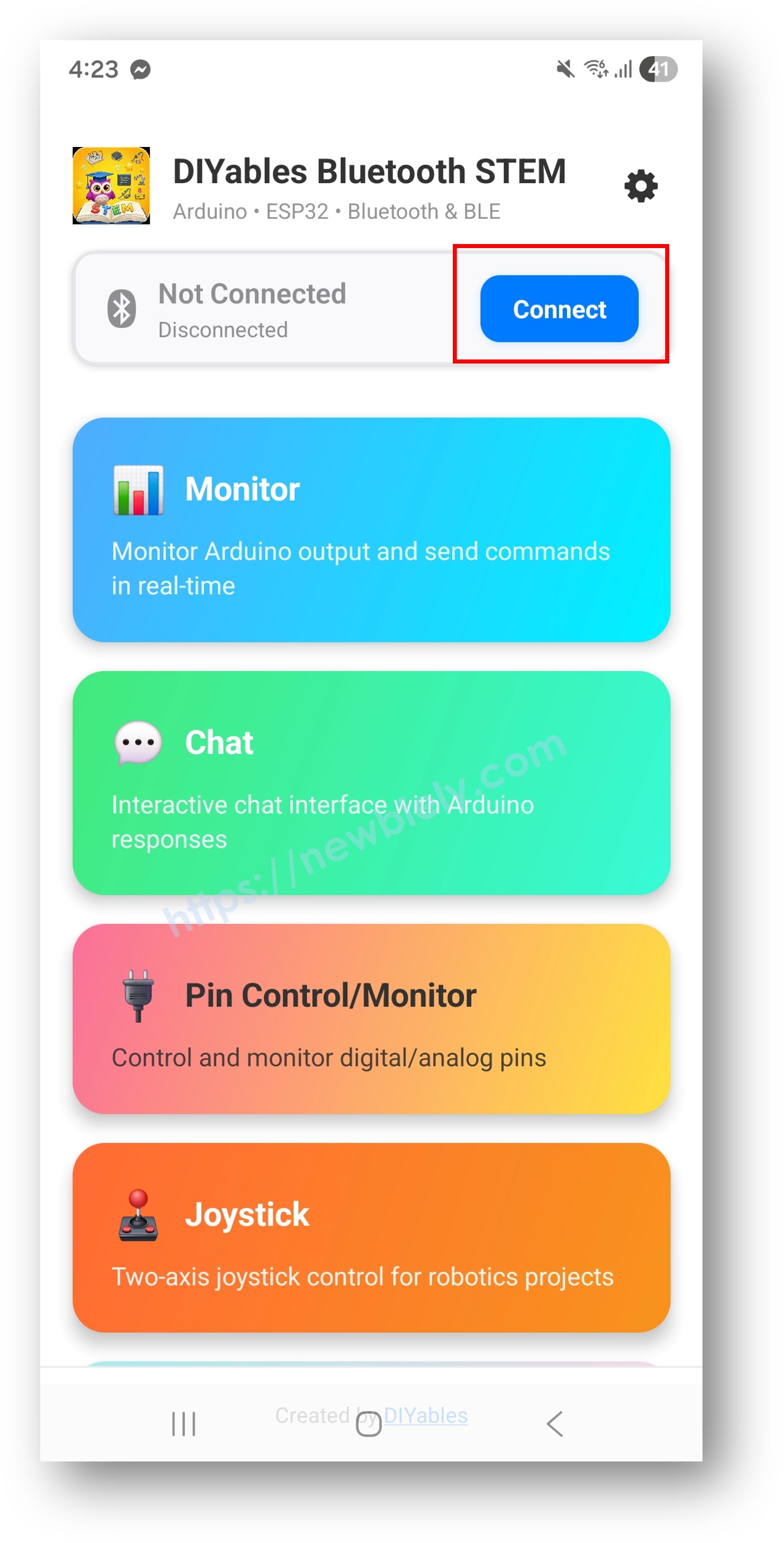
Open the DIYables Bluetooth App
When opening the app for the first time, it will ask for permissions. Please grant the following:
Nearby Devices permission (Android 12+) / Bluetooth permission (iOS) - required to scan and connect to Bluetooth devices
Location permission (Android 11 and below only) - required by older Android versions to scan for BLE devices
Make sure Bluetooth is turned on on your phone
On the home screen, tap the Connect button. The app will scan for both BLE and Classic Bluetooth devices.
Find and tap your device in the scan results to connect:
For Classic Bluetooth: tap "ESP32_Pins"
For BLE: tap "ESP32BLE_Pins"
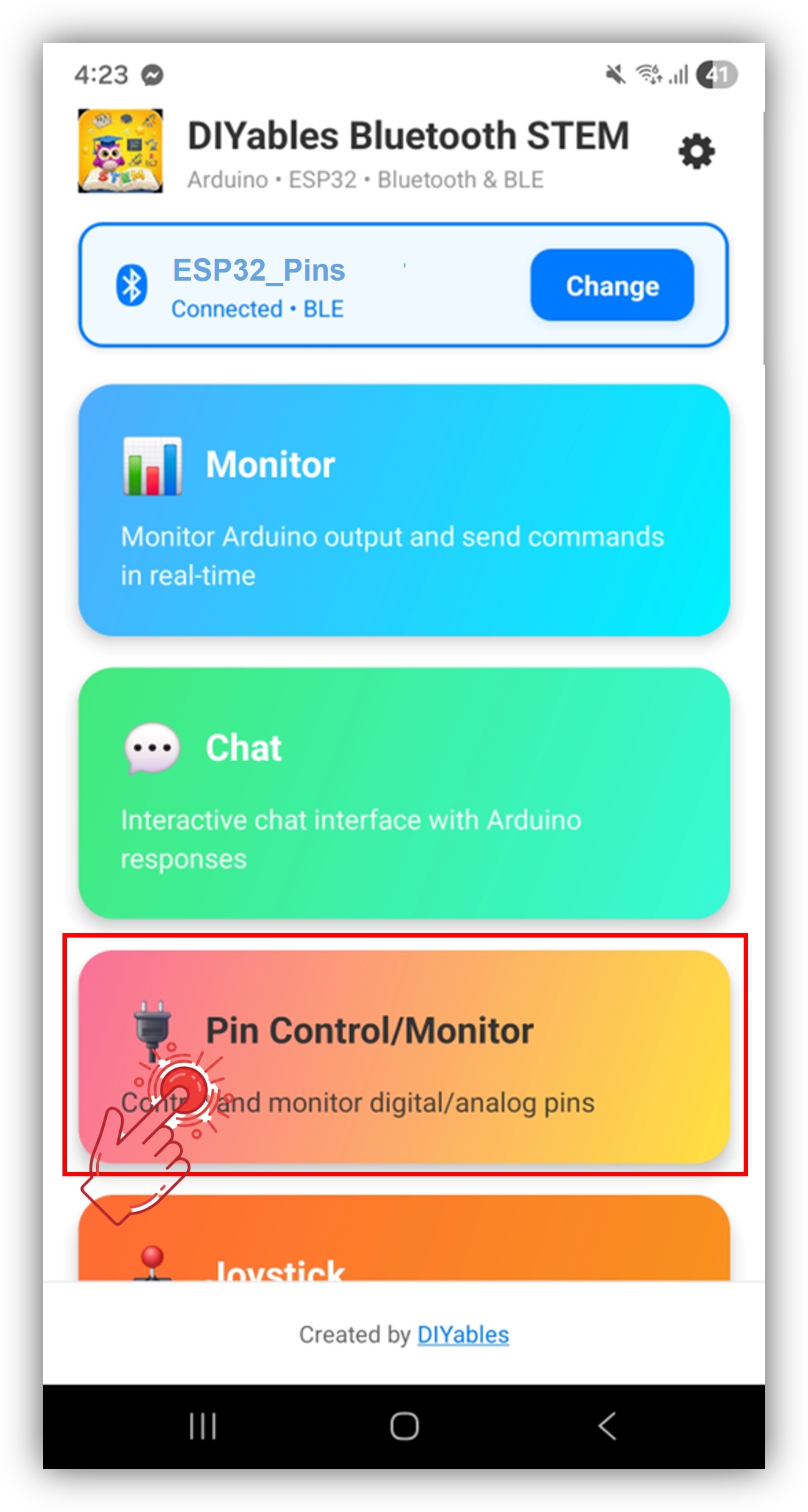
Once connected, the app automatically goes back to the home screen. Select the Digital Pins app from the app menu.
Note: You can tap the settings icon on the home screen to hide/show apps on the home screen. For more details, see the DIYables Bluetooth App User Manual.
Toggle output pins by tapping on them, and watch input pins update in real time
Now look back at the Serial Monitor on Arduino IDE. You will see:
Newbiely | Arduino IDE 2.3.8
──
☐
✕
File
Edit
Sketch
Tools
Help
ESP32 Dev Module
Newbiely.ino
···
8Serial.println("Hello World!");
Output
Serial Monitor
Message (Enter to send message to 'ESP32 Dev Module' on 'COM15')
New Line
9600 baud
Bluetooth connected!
Pin 2 set to HIGH
Pin 16 set to LOW
Input pin 18 changed to LOW
Analog pin 34 changed to 2048
Ln 11, Col 1
ESP32 Dev Module on COM15
2
Toggle pins in the app and watch the real-time feedback in the Serial Monitor
Creative Customization - Adapt the Code to Your Project
Configure Pins
Enable pins with custom names and modes:
// Enable individual pins with mode and custom namebluetoothPins.enablePin(2, BT_PIN_OUTPUT, "LED"); // Built-in LEDbluetoothPins.enablePin(16, BT_PIN_OUTPUT, "Relay1"); // Relay controlbluetoothPins.enablePin(17, BT_PIN_OUTPUT, "Relay2"); // Relay controlbluetoothPins.enablePin(18, BT_PIN_INPUT, "Button"); // Button inputbluetoothPins.enablePin(34, BT_PIN_INPUT, "Sensor"); // Analog sensor// Disable a specific pinbluetoothPins.disablePin(17);// Check pin statusbool isEnabled = bluetoothPins.isPinEnabled(2);int mode = bluetoothPins.getPinMode(2);int count = bluetoothPins.getEnabledPinCount();
Handle Pin Write Commands
Use the onPinWrite() callback to control hardware when the app toggles a pin:
bluetoothPins.onPinWrite([](int pin, int state) {digitalWrite(pin, state);Serial.print("Pin ");Serial.print(pin);Serial.print(" set to ");Serial.println(state ? "HIGH" : "LOW");});
Handle Pin Read Commands
Use the onPinRead() callback to return pin states to the app:
bluetoothPins.onPinRead([](int pin) -> int {if (pin == 34 || pin == 35) {// Read analog value for ADC pinsreturnanalogRead(pin); } else {// Read digital value for other pinsreturndigitalRead(pin); }});
Handle Pin Mode Changes
Use the onPinModeChange() callback to dynamically change pin modes:
bluetoothServer.setOnConnected([]() {Serial.println("Bluetooth connected!");});bluetoothServer.setOnDisconnected([]() {Serial.println("Bluetooth disconnected!");// Safety: turn off all outputs when disconnecteddigitalWrite(2, LOW);digitalWrite(16, LOW);digitalWrite(17, LOW);});
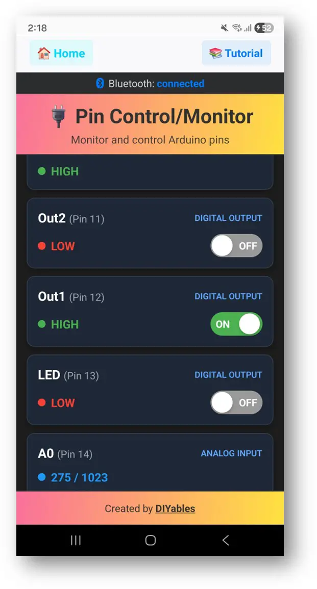
How to Use the Digital Pins
App Interface Controls
The digital pins interface in the DIYables Bluetooth App provides:
Pin List: Shows all enabled pins with names and current states
Toggle Buttons: Tap output pins to toggle HIGH/LOW
Input Display: Real-time display of input pin states
Analog Values: Shows raw analog values for ADC pins
Pin Modes
BT_PIN_OUTPUT (0): Controls digital output — toggle from the app
BT_PIN_INPUT (1): Monitors digital or analog input — displays current state
Please feel free to share the link of this tutorial. However, Please do not use our content on any other websites. We invested a lot of effort and time to create the content, please respect our work!