
ESP32 - BTS7960 Motor Driver
A garden cart full of soil bags, plant pots or a big watering can gets heavy fast. Pushing it up a grassy slope is hard work. Fit a 12V gear motor to one wheel, let an ESP32 be the brain, and you have the start of a remote-controlled garden cart. Later, the ESP32 can take your orders from a phone over WiFi or Bluetooth. But a motor that moves a loaded cart needs much more current than a small driver chip is built for. So this project uses the DIYables BTS7960 43A motor driver module. Many shops call the same board IBT-2. On this page, the ESP32 makes one 12V DC motor start slowly, reach full speed, slow down, brake, reverse and roll free. Four GPIO pins and a short sketch do all of it, with no library.
This tutorial shows how to program the ESP32 using the Arduino language (C/C++) via the Arduino IDE. If you’d like to learn how to program the ESP32 with MicroPython, visit this ESP32 MicroPython - BTS7960 Motor Driver tutorial.
Hardware Used In This Tutorial
Or you can buy the following kits:
| 1 | × | DIYables ESP32 Starter Kit (ESP32 included) | |
| 1 | × | DIYables ESP32 S3 Starter Kit (ESP32 S3 included) | |
| 1 | × | DIYables Sensor Kit (18 sensors/displays) |
Pick jumper wires with a female plug on both ends for the six control wires, since the ESP32 pins and the BTS7960 header pins are all male. For B+ and B-, short pieces of heavier wire from the DC power jack work better than jumper wires, because the whole motor current runs through them.
Introduction to BTS7960 Motor Driver
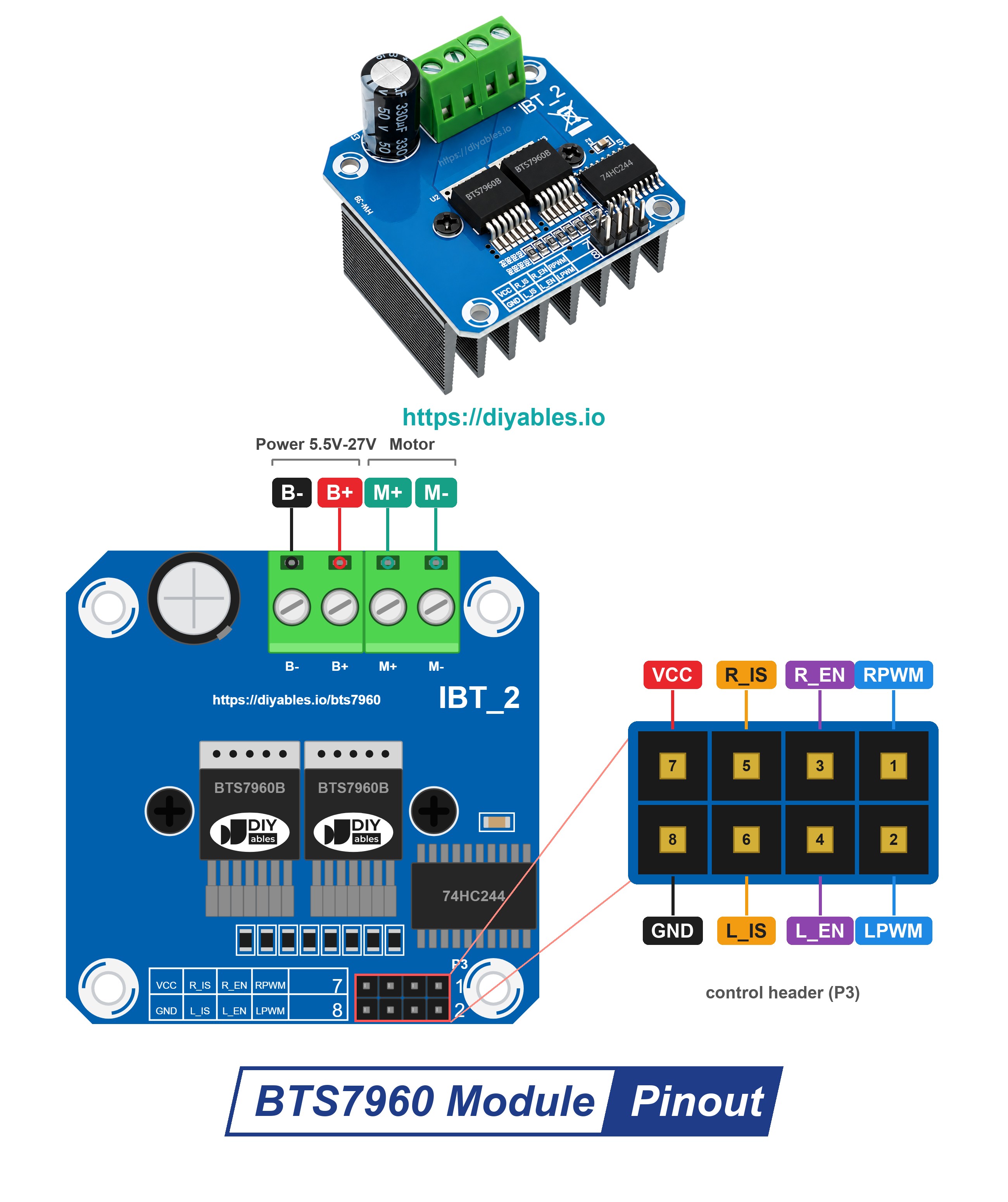
The BTS7960 board is built to drive one big brushed DC motor. Two Infineon BTS7960B power chips are mounted on top of the board. Think of each chip as a two-way switch for one motor wire: it puts that wire on the + or on the - of the motor supply. Such a chip is called a half-bridge. Put one on each motor wire, and the pair becomes a full H-bridge. Now the current can flow through the motor in either direction, and the cart can drive ahead or back up. Speed is a matter of PWM: with the code on this page, the 12V to the motor is switched on and off about 1000 times per second. The more time the 12V is on in each cycle, the faster the motor turns. Below the board, a big heat sink keeps the two chips cool. One more chip sits on the logic side: a 74HC244 buffer. It takes the signals from the ESP32 and passes them to the two power chips, so the ESP32 pins only drive this small chip.
L298N and DRV8833 boards are made for small motors. A loaded cart needs more. So do winches, scooters, wheelchairs, heavy robots, and big gear or wiper motors in general. This is where the BTS7960 comes in.
| BTS7960 Motor Driver Module | |
|---|---|
| The power chips | 2 x Infineon BTS7960B half-bridges (one full H-bridge) |
| The motor it drives | one brushed DC motor, both directions |
| The motor supply (B+ and B-) | 5.5V to 27V DC (a 24V, 12V or 6V system is fine) |
| The current | 43A peak (the chips limit the current at this level) |
| The PWM frequency | up to 25kHz on RPWM and LPWM |
| The logic chip | 74HC244 buffer, fed by the VCC pin |
| The protection | current limiting, over-temperature protection |
What does 43A mean for the cart? It is a peak: once the current climbs that high, the protection inside the chips kicks in. A motor that drives the cart around the garden for an hour must stay far lower. On long runs, heat is the real limit, and the heat sink decides what the board can handle.
BTS7960 Pinout
The 8-pin header is easy to read. The odd pin numbers (1, 3, 5, 7) form the "R" row: RPWM, R_EN, R_IS and VCC. The even numbers (2, 4, 6, 8) form the "L" row: LPWM, L_EN, L_IS and GND. The silkscreen shortens the two sense pins to R_S and L_S.
- RPWM pin: connect this pin to GPIO16. A PWM signal here drives the cart forward (right half-bridge).
- LPWM pin: connect this pin to GPIO17. A PWM signal here makes the cart back up (left half-bridge).
- R_EN pin: connect this pin to GPIO19. The right half-bridge works only while this pin is HIGH.
- L_EN pin: connect this pin to GPIO18. Same idea, for the left half-bridge.
- VCC pin: connect this pin to VIN (5V from USB). Only the 74HC244 and the power LED run on it. The motor current never flows through this pin.
- GND pin: connect this pin to GND of the ESP32. On the board, it is tied to B-.
- R_IS and L_IS pins: outputs for current sense and error signals. This project leaves them without a wire.
- B+ and B- screw terminals: the 12V input, wired to the DC power jack (+ to B+, - to B-).
- M+ and M- screw terminals: the motor leads screw in here.
Pedals and Main Switch: Driving the Cart
Think of the two enable pins as the main switch of the cart, and of the two PWM pins as two pedals: one for driving ahead and one for backing up. The PWM value, from 0 to 255, says how far the pedal is pushed down.
| Cart move | R_EN, L_EN | RPWM | LPWM |
|---|---|---|---|
| Drive ahead (a bigger value goes faster) | HIGH | PWM 0 to 255 | 0 |
| Back up (a bigger value goes faster) | HIGH | 0 | PWM 0 to 255 |
| Brake (the driver ties the motor leads together, quick stop) | HIGH | 0 | 0 |
| Coast (both half-bridges off, the motor spins down on its own) | LOW | 0 | 0 |
Only one pedal at a time: RPWM and LPWM must never both get PWM, so one of them is always 0. Brake or coast? Brake is what the cart needs at the end of the path, where it must stop quickly. Coast is the soft choice: the cart rolls on a little and slows down by itself.
Powering the Cart Motor
Two supplies work side by side here. The USB cable feeds the ESP32. The 12V adapter feeds the motor, through the DC power jack into B+ and B-. Choose an adapter rated for more amps than the motor draws, plus some margin.
VCC goes to the VIN pin, which carries the 5V from the USB cable. VCC feeds nothing but the small buffer chip, and the maker of the module asks for 5V there. The control pins take 3.3V signals, so the ESP32 GPIO pins can drive them directly. Each control input has a pull-down resistor, and R_IS and L_IS have no wire, so the signals only go from the ESP32 to the module, never back. So the 5V cannot reach the ESP32 pins.
The ground needs no extra work. The GND pin of the header and the B- screw are one and the same point on the board. So the GND jumper from the ESP32 also links the ESP32 to the minus side of the 12V adapter, and both sides share one ground.
WARNING
B+ carries the full 12V, so it must never touch the ESP32. Before the first power-on, read the + and - signs printed next to the screws of the DC power jack, and follow them: + to B+, - to B-. Mixed up, they can damage the module.
Already own an L298N? Here is how the two drivers differ:
| Driver | Motors | Current | Voltage lost inside |
|---|---|---|---|
| L298N | two | about 2A each | about 2V |
| BTS7960 | one | up to 43A (peak) | very little |
For small motors, a smaller driver is the easier choice: the DRV8833. See ESP32 - DRV8833 DC Motor Driver or ESP32 - DC Motor.
Wiring Diagram
The diagram keeps the wires tidy. The ESP32 sends its four control signals from GPIO16, GPIO17, GPIO18 and GPIO19, which are close together on one header, and the GND wire starts from that header too. The VIN wire is the only one that crosses over from the header on the other side. At the module, the six wires fill the 8-pin header, except R_IS and L_IS. The motor and the 12V supply use the four big screw terminals.
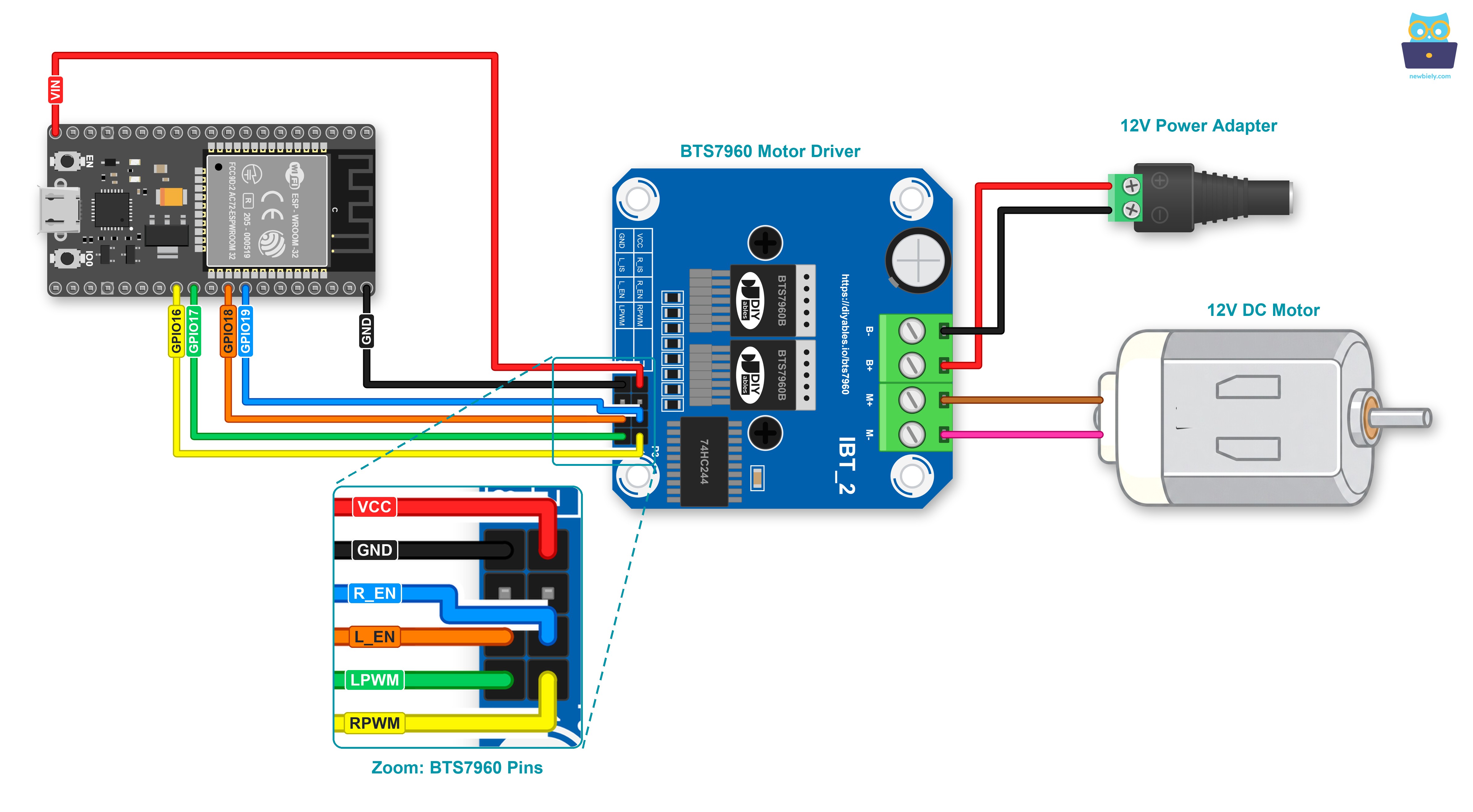
This image is created using Fritzing. Click to enlarge image
| BTS7960 Module | ESP32 / Other |
|---|---|
| RPWM | → GPIO16 |
| LPWM | → GPIO17 |
| R_EN | → GPIO19 |
| L_EN | → GPIO18 |
| VCC | → VIN (5V from USB) |
| GND | → GND |
| R_IS, L_IS | (left free) |
| B+ | → + screw of the DC power jack |
| B- | → - screw of the DC power jack |
| M+, M- | → the two motor leads |
※ NOTE THAT:
Wire with everything switched off: no USB cable, no 12V adapter. The 12V adapter is plugged in last of all.
How were these pins picked? Every output GPIO of the ESP32 can make PWM, so the choice is about safety and short wires. GPIO16 to GPIO19 have no job while the ESP32 boots (none of them is a strapping pin), so the board starts normally with the module wired. GPIO16 and GPIO17 are free on the ESP32-WROOM-32 module of this board. On a board with an ESP32-WROVER module, these two belong to the PSRAM. There, move RPWM and LPWM to two other free pins, for example GPIO25 and GPIO26, and change the two numbers in the code. Stay away from GPIO6 to GPIO11 (used by the flash) and GPIO34 to GPIO39 (input only).
If you're unfamiliar with how to supply power to the ESP32 and other components, you can find guidance in the following tutorial: The best way to Power ESP32 and sensors/displays.
How To Program For the BTS7960 Driver
No library is needed. analogWrite() handles RPWM and LPWM, and digitalWrite() handles R_EN and L_EN. The code wraps them in two small helpers, so loop() reads like a list of cart moves.
- Name the pins by their GPIO numbers:
- DriveMotor() takes one signed speed, from -255 to 255. It always clears the opposite PWM pin before it gives PWM to the other one:
- SetDriver() switches both half-bridges at once:
- In setup(), after pinMode() for all four pins, the order matters: PWM to zero first, driver on last:
- With the helpers, each cart move takes one line:
On the ESP32, analogWrite() makes PWM at about 1kHz, far below the 25kHz limit of the driver. A soft hum or whine from the motor at low speed comes from this PWM, and it is normal.
ESP32 Code - BTS7960 Motor Driver
One trip of the garden cart runs in a loop: a slow start, full speed, a gentle stop, a hard brake, a short run in reverse at half speed, and a free roll at the end. Each part prints a numbered line, which tells you what the motor should be doing right now. At the end of a trip, setDriver(true) turns the driver back on for the next one.
Quick Instructions
- If this is the first time you use ESP32, see how to setup environment for ESP32 on Arduino IDE.
- Wire the ESP32 to the header of the module as in the diagram above. Then fasten the motor leads in M+ and M-, and the two wires from the DC power jack in B+ and B-. Do not connect the 12V adapter at this step.
- Make sure the motor can spin freely. If it is already on the cart, lift the wheel off the ground.
- Plug the USB Type-C cable into the ESP32 and into your PC.
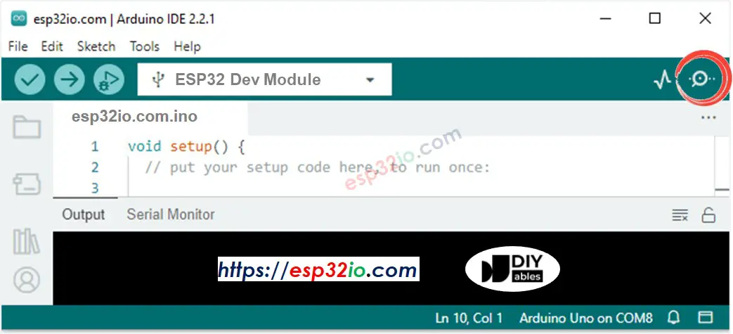
- Start Arduino IDE and choose the right ESP32 board (e.g. ESP32 Dev Module) and COM port.
- Start a new sketch in Arduino IDE and replace its contents with the code above. No library is needed for this.
- Click to the Upload button on Arduino IDE to compile the code and upload it to the ESP32.
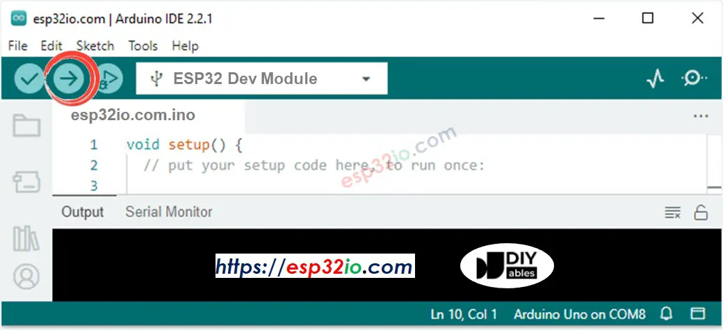
- When the upload is done, connect the 12V adapter to the wall socket. The motor wakes up and starts the trip.
- Open the Serial Monitor and set the baud rate to 9600.
- To see the start line too, press the EN button on the ESP32 once.
- Watch the motor and the Serial Monitor together for one or two trips.
Keep your ears on the motor in parts [1] and [3]: the sound climbs and falls with the speed. Then compare [4] and [6]. With the brake, the shaft stops nearly at once. With the coast, it spins down slowly, because nothing holds it back. If the cart would back up during [1] instead of driving ahead, exchange the motor leads on M+ and M-. No change in the code is needed.
※ NOTE THAT:
Lines in the Serial Monitor, but no movement? Go through this list:
- Look at the power LED of the module. If it is dark, the logic chip has no power: check the VIN and GND jumpers.
- Check GPIO19 to R_EN and GPIO18 to L_EN. If either enable pin is not HIGH, the motor cannot move either way.
- Check that the 12V adapter sits in the wall socket, and that B+ and B- really get its + and -.
What next? Turn the timed trip into a real remote control. Read a TV remote with ESP32 - IR Remote Control, a stick on a cable with ESP32 - Joystick, or buttons on a phone web page with ESP32 - Controls Car via Web. Then call driveMotor() with the speed that each command asks for.
Line-by-line Code Explanation
Every important line of the ESP32 code has a comment. Read the code and its comments side by side!
Video Tutorial
Making video is a time-consuming work. If the video tutorial is necessary for your learning, please let us know by subscribing to our YouTube channel , If the demand for video is high, we will make the video tutorial.